Build guide
Welcome to the build guide! Before you assemble, make sure you grab everything you need– tools, printed parts and ordered parts. All hardware is M3 unless otherwise stated.
-
Print the parts
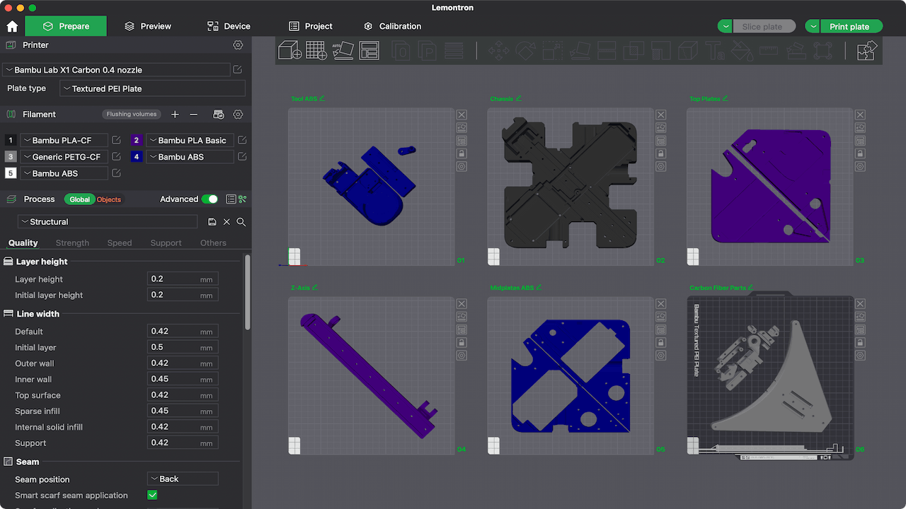 Check out the Printed Parts page for important information.
 -
Install the software
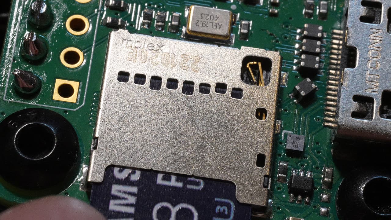 Use the Software Guide to install the required software on to the Raspberry Pi and SKR Pico. The SKR Pico is hard to reach once the Lemontron is assembled!
 -
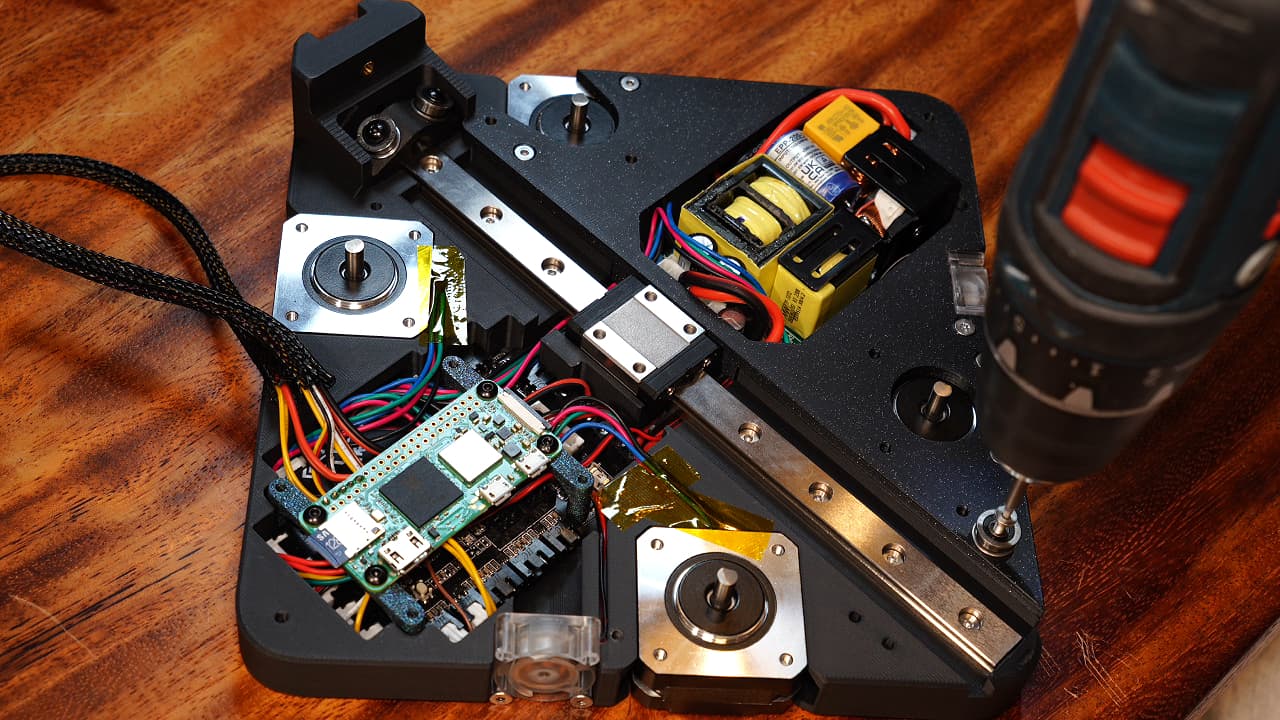
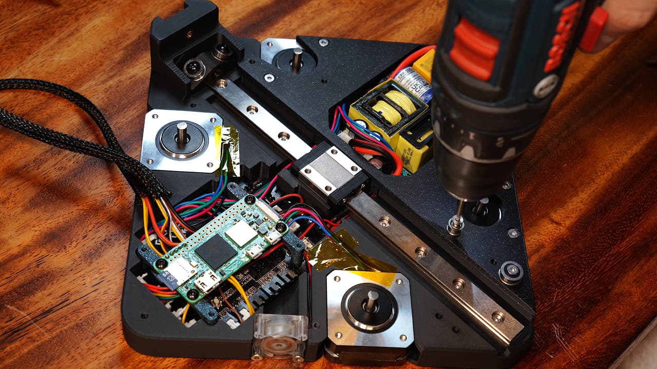
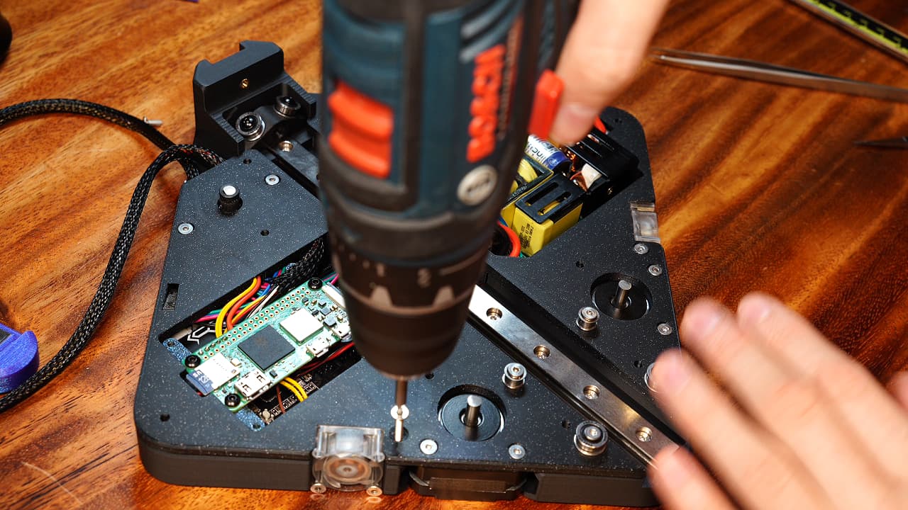
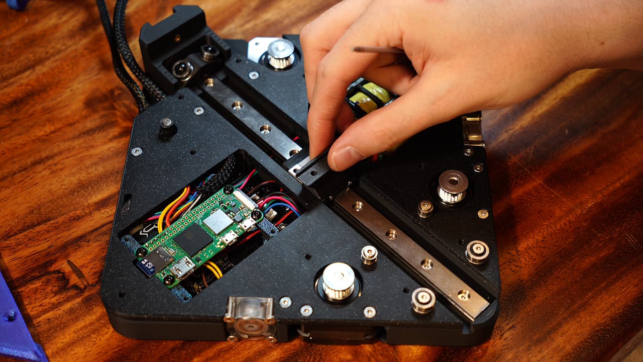
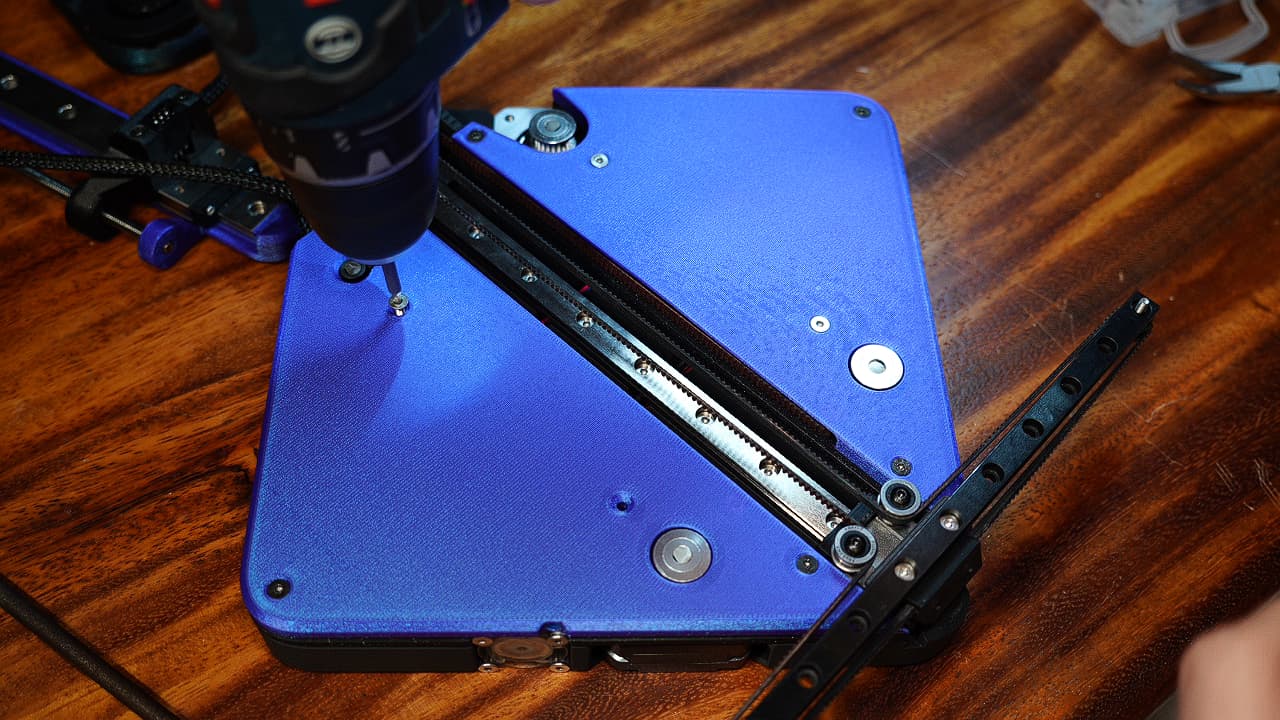
Insert the screws
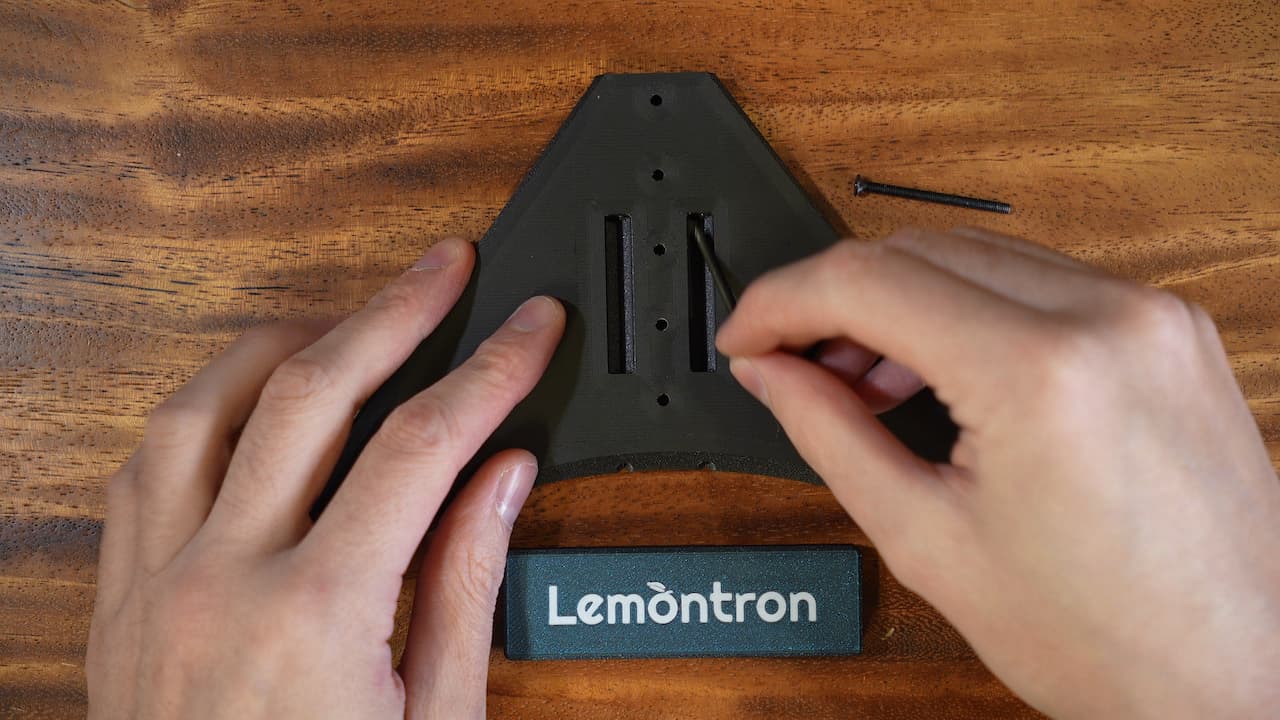 Drop two screws into the holes.
 M340mm
 -
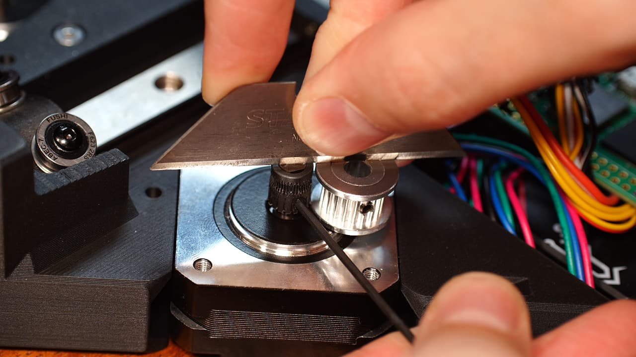
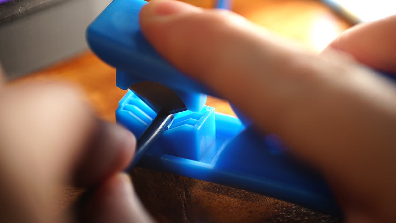
Scrape the mating surface flat
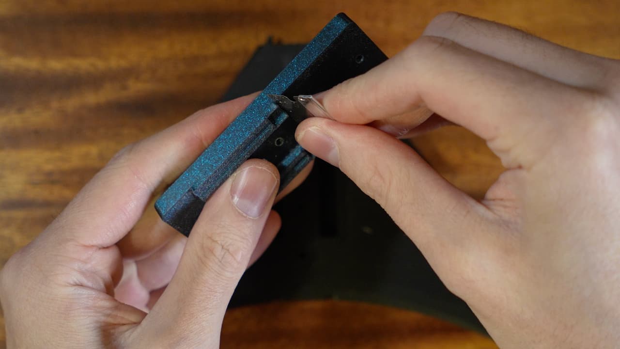 Using a blade, lightly scrape the surface. This will remove any gaps and make the parts fit together beautifully.
 -
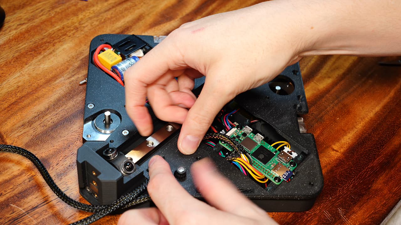
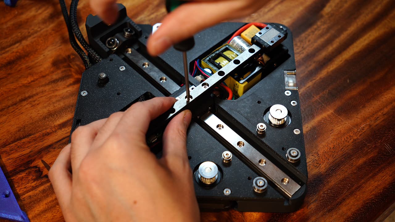
Screw in the spine
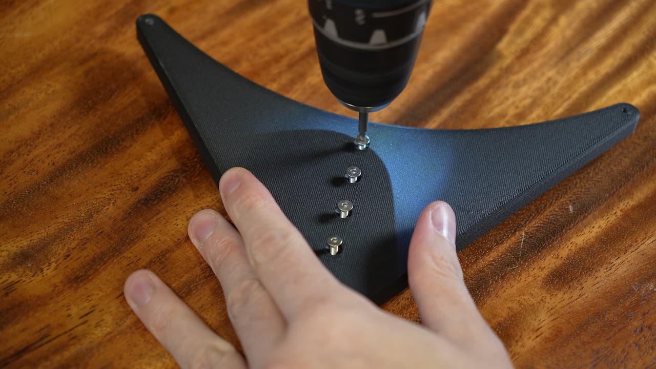 Secure it with 5 screws.
 M314mm
 -
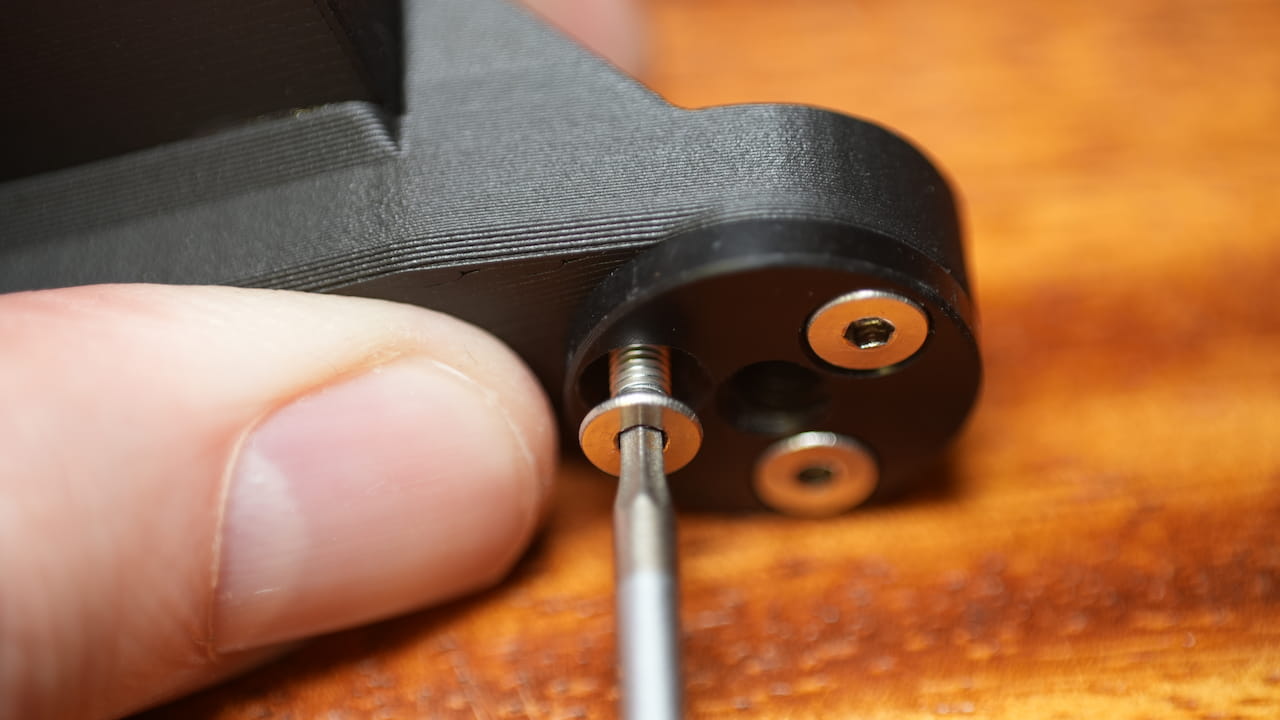
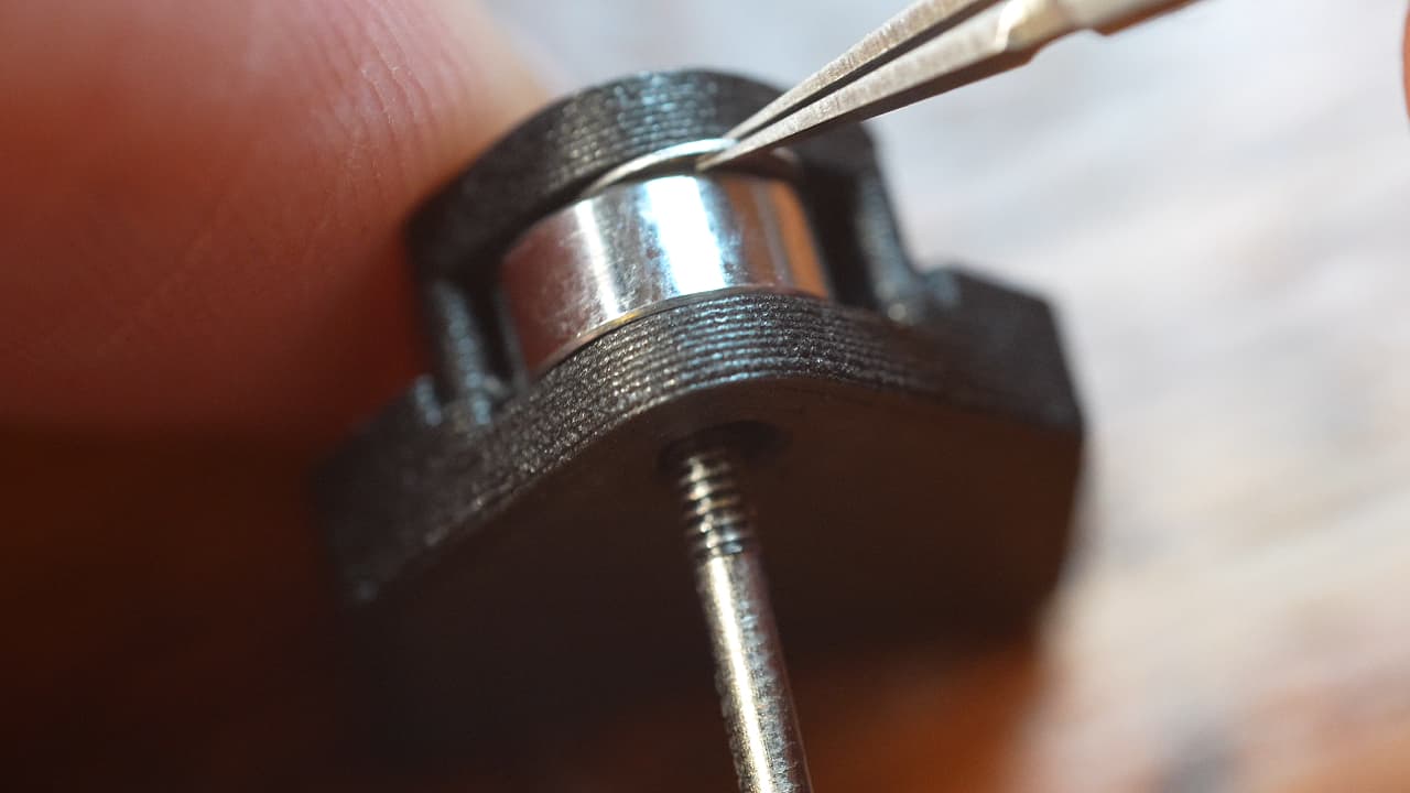
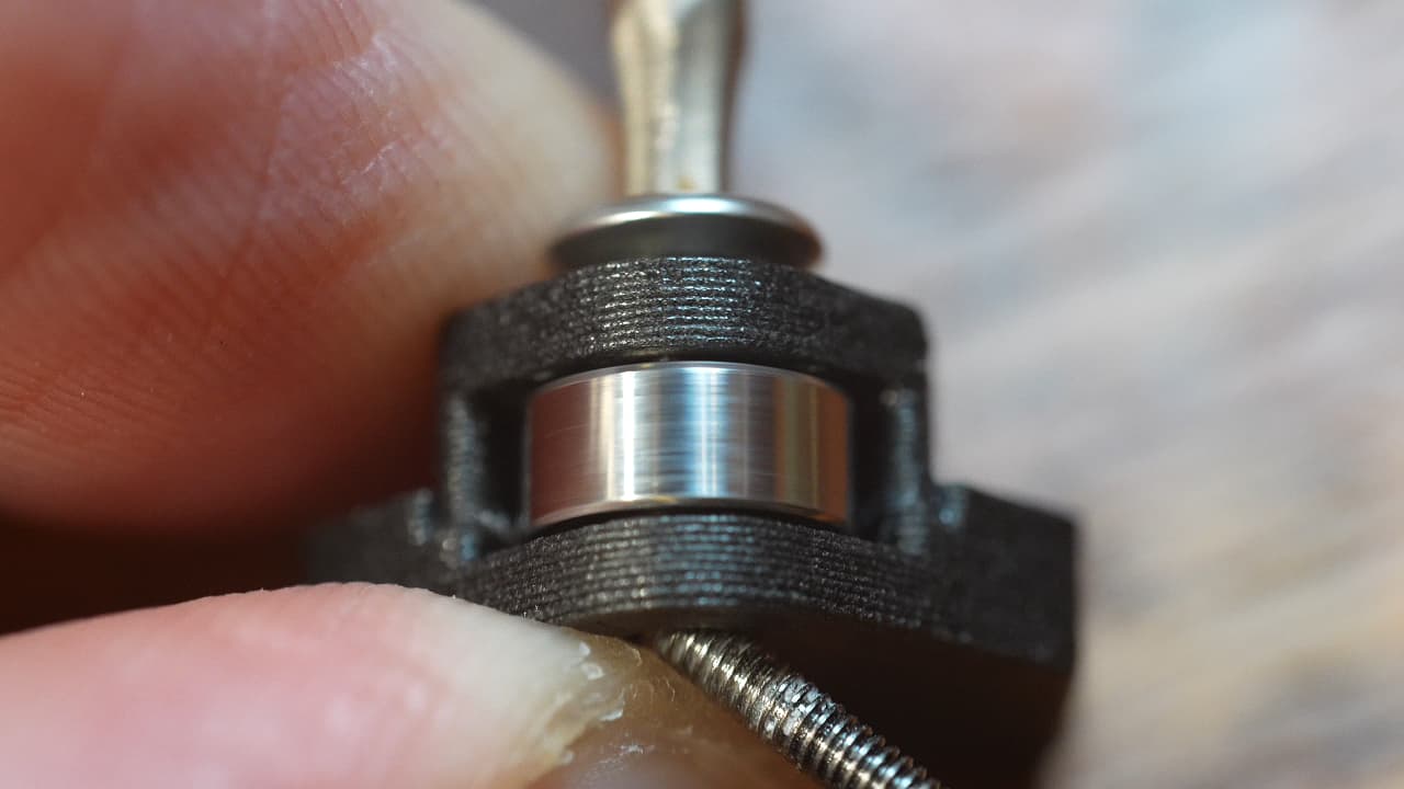
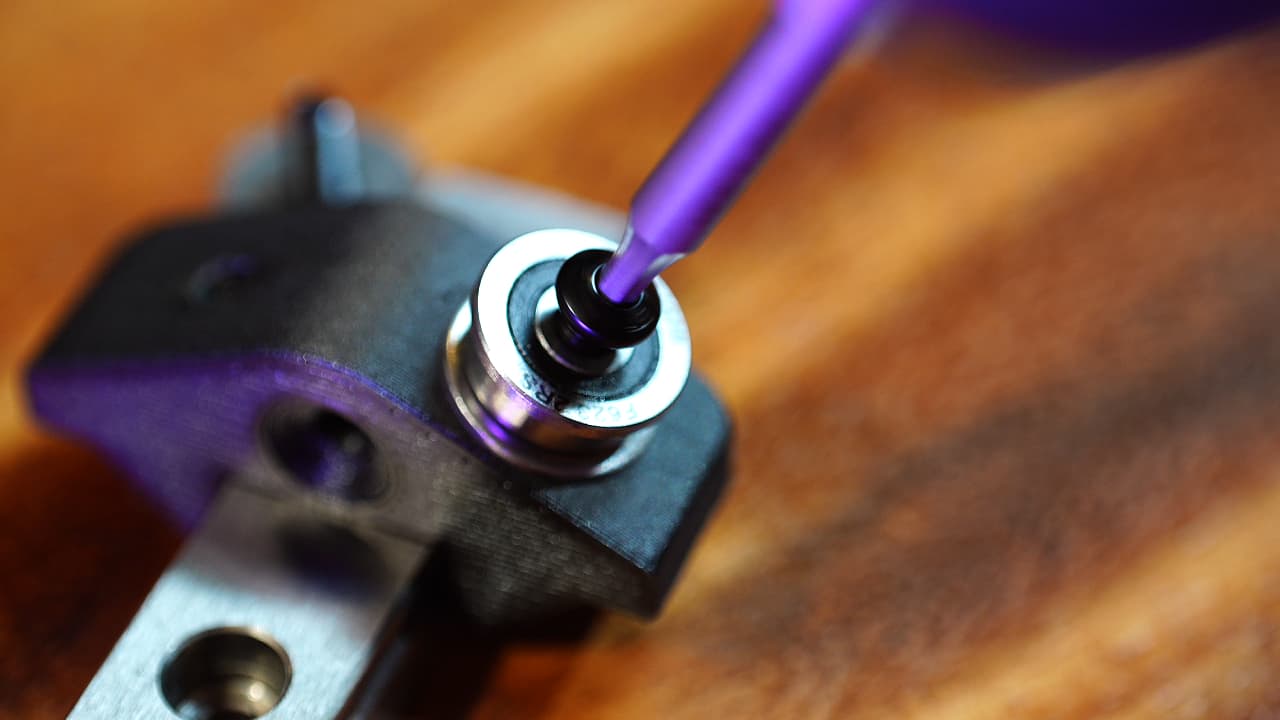
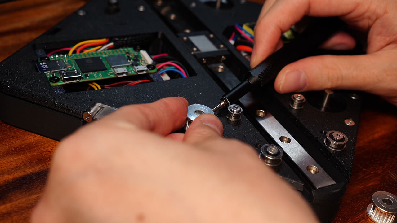
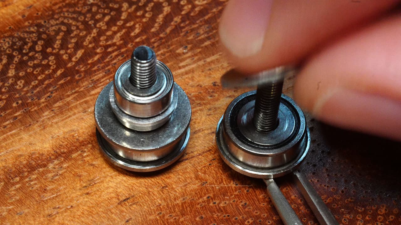
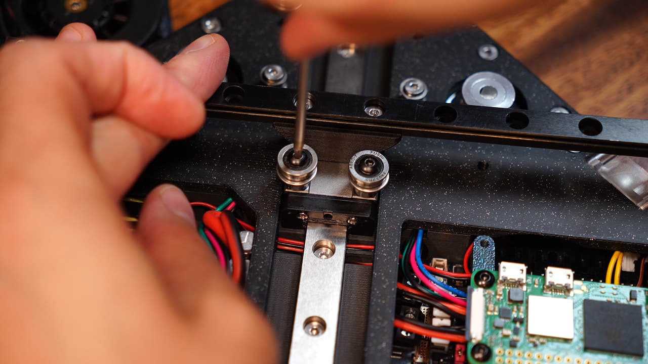
Install the posts
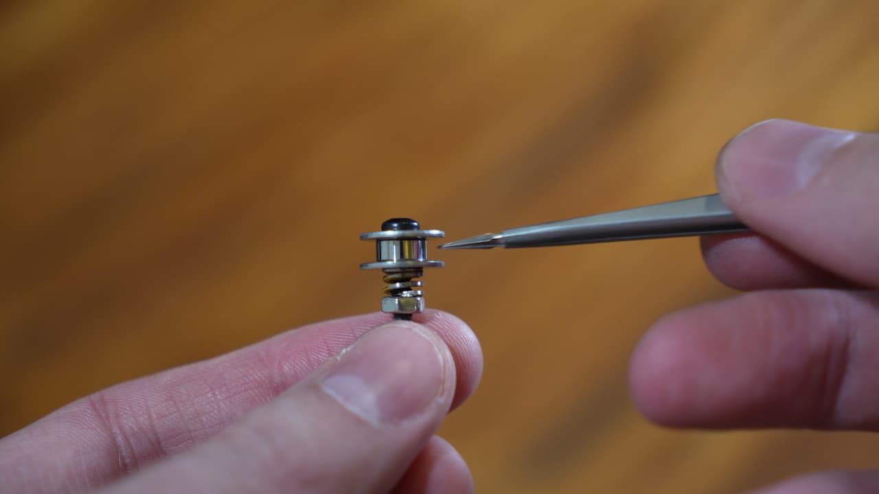 Onto the screws, drop a 12mm washer, small bearing, another washer, a yellow spring that's been cut in half, and a nut.
M320mm
Onto the screws, drop a 12mm washer, small bearing, another washer, a yellow spring that's been cut in half, and a nut.
M320mm -
Gather Z-Axis parts
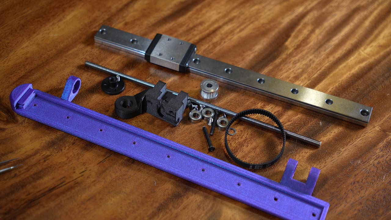 Gather the Z axis (printed), bracket (printed), MGW9C linear rail, 6 × 3d-printed spacers, 6 × 8mm countersunk screws, 2 × 25mm wafer head screws, M5 shims, M5 bearings, lead screw & nut, drive pulley and belt.
 -
Insert the bearings
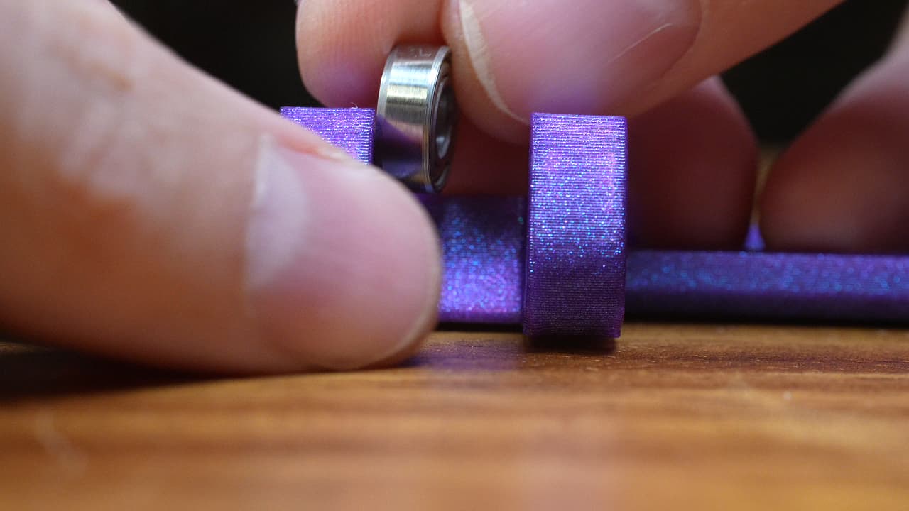 Insert 3 MR115 bearings into the seats.Or, you can actually omit the top bearing if you want.
 -
Insert the lead screw
 Insert the lead screw through so that it just pokes through the bottom bearing.
 -
Drop in the first shim
 Drop in the first shim. This shim allows the bearing to turn while pressing against the drive pulley.
 -
Drop in the drive pulley
 Drop in the drive pulley with the belt pre-installed. Advance the lead screw flush with the top of the pulley.
 -
Fish in the second shim
 Use something thin to fish in the second shim. Push the lead screw all the way through.
 -
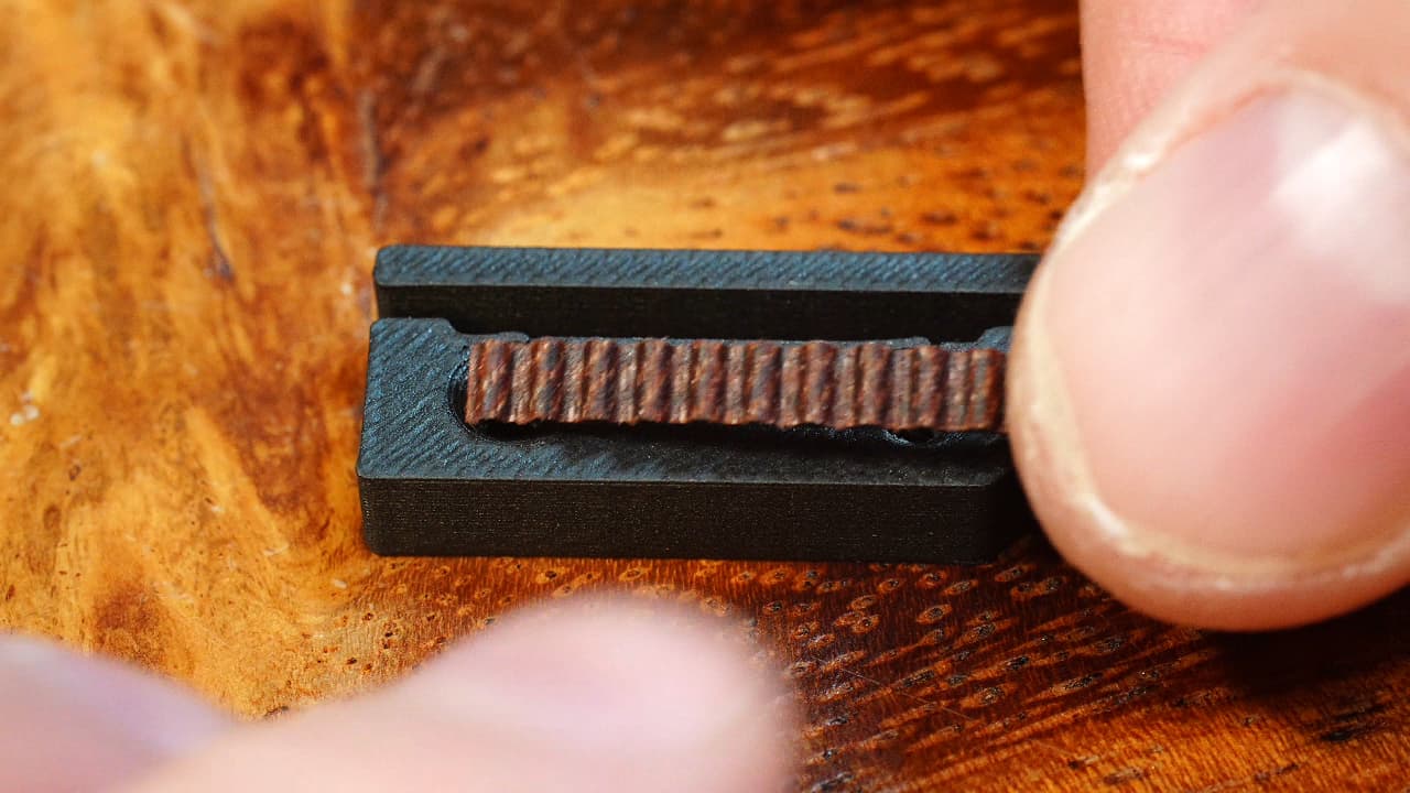
Glue the bracket
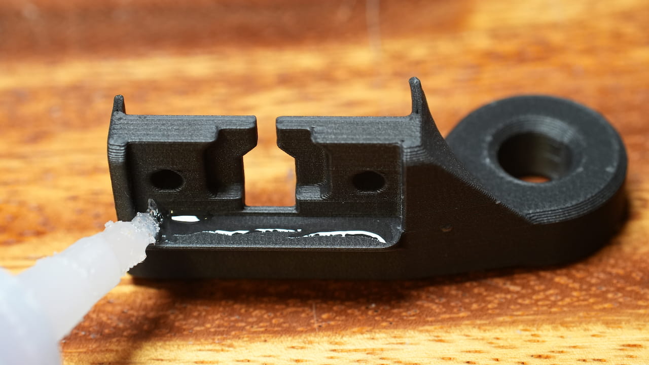 Dap some supa glue on the ledge on the bracket.
 -
Press & dry the glue
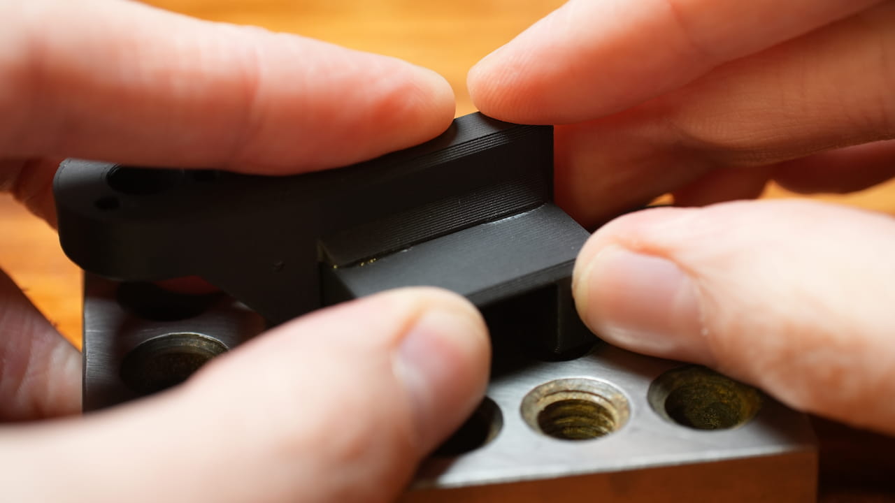 Press the top of the bracket onto a flat surface while it dries.
 -
Clip off the support
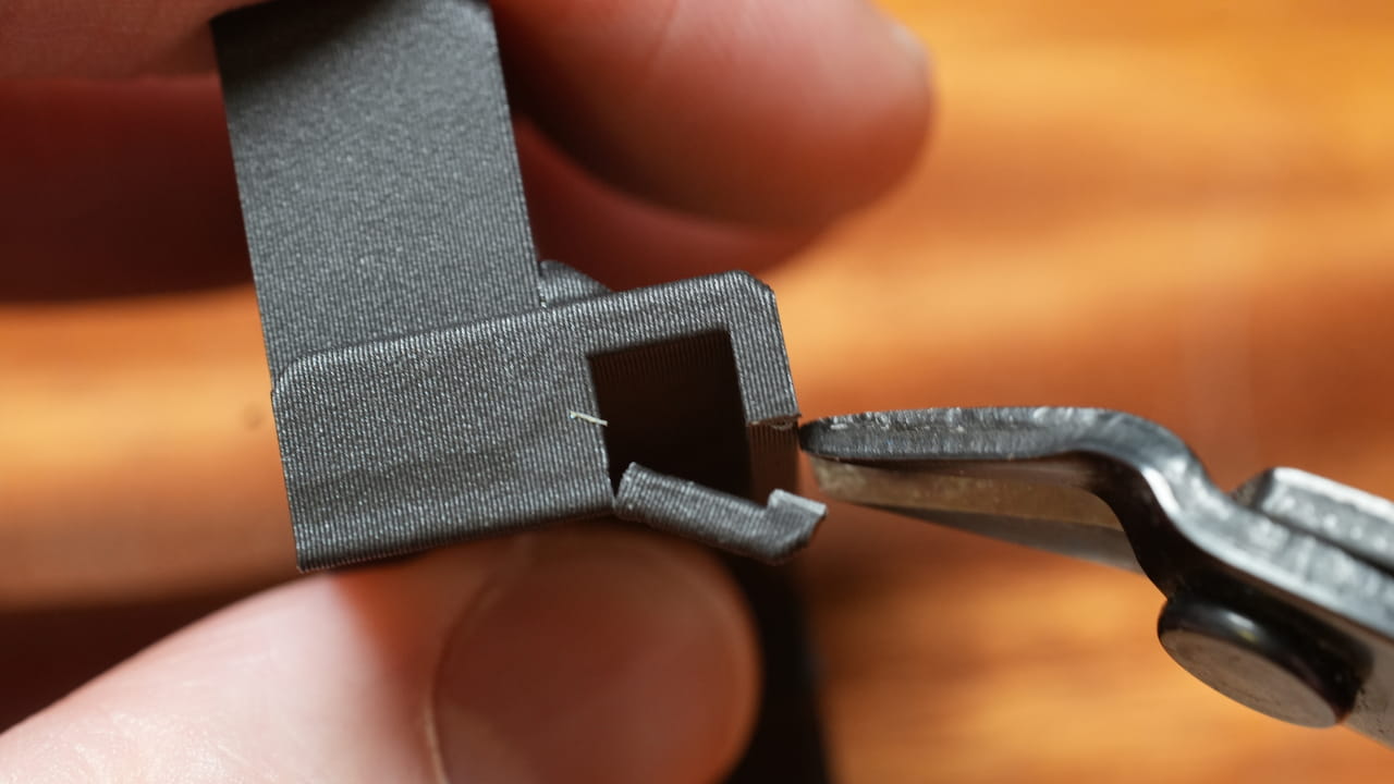 Clip off the support from the bottom with flush cutters.
 -
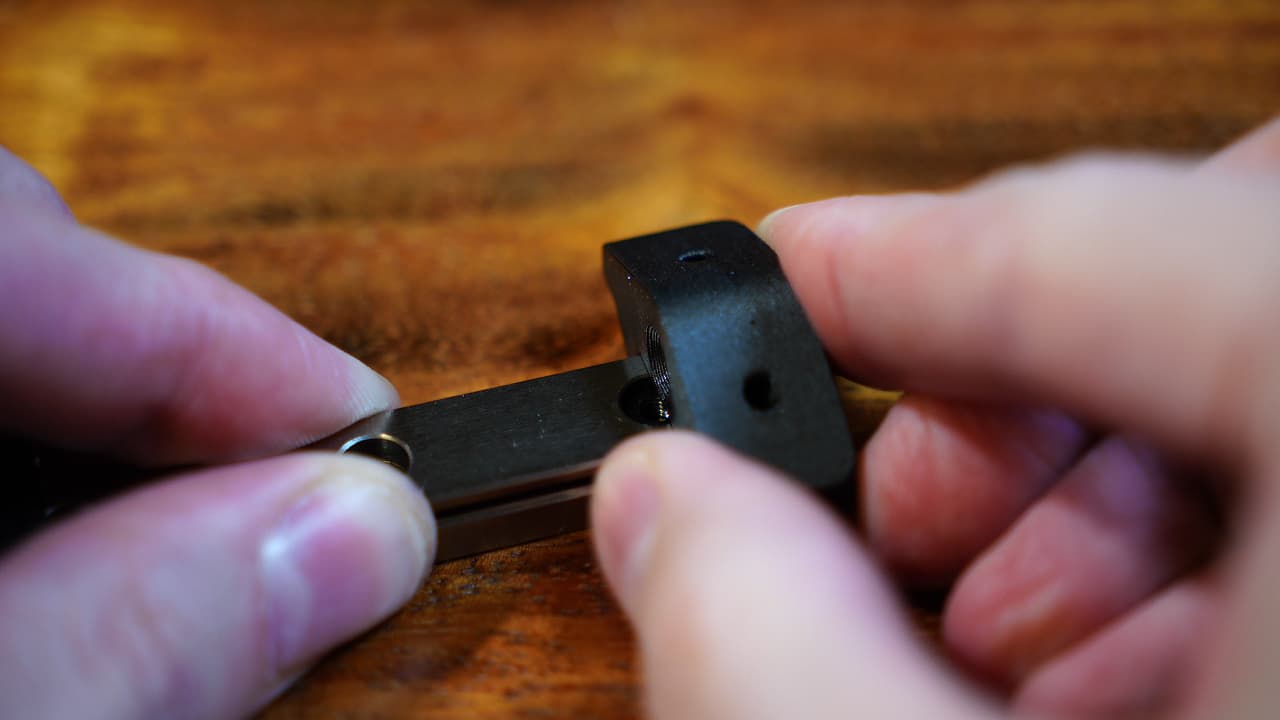
Insert the lead nut
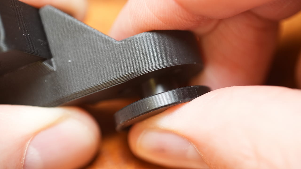 Insert the nut that came with the lead screw to the bracket.
 -
Attach the lead nut
 Attach the lead nut to the bracket.
M38mmIf your nut isn't countersunk, countersink it.
Attach the lead nut to the bracket.
M38mmIf your nut isn't countersunk, countersink it. -
Add the bracket
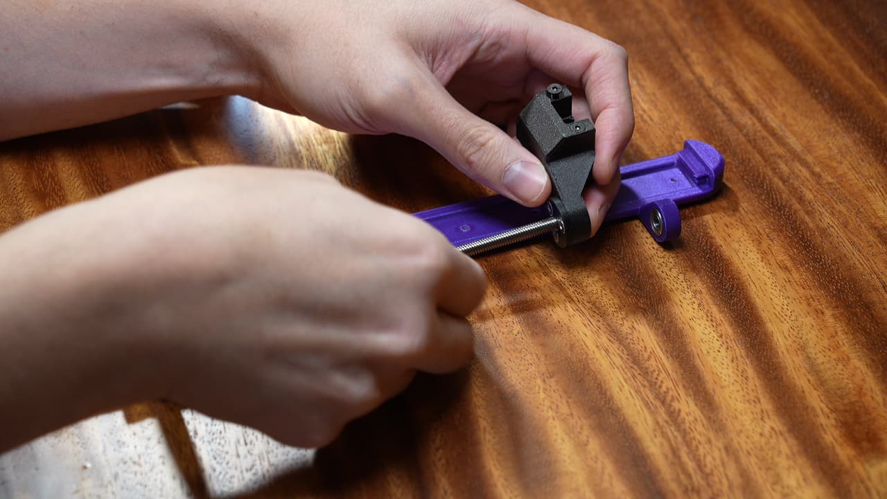 Install the bracket onto the lead screw.
 -
Cut the lead screw
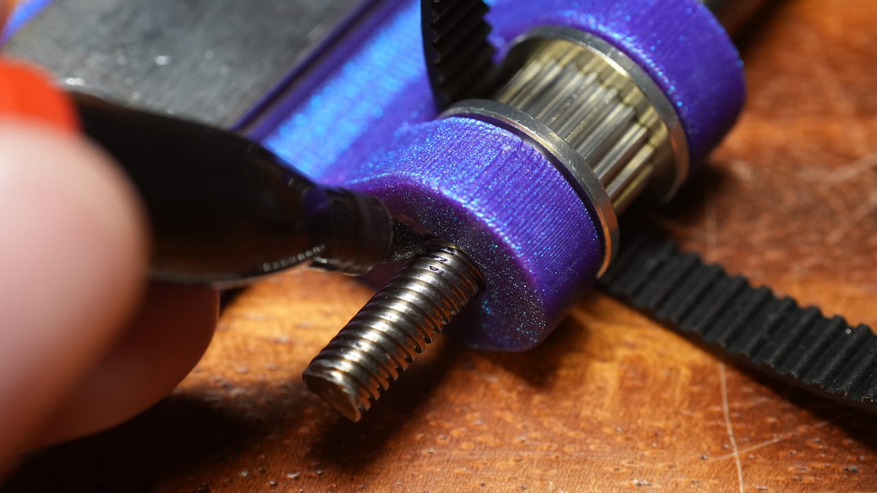 Align the lead screw's top with the top of the bearing seat and CUT the bottom off.
 -
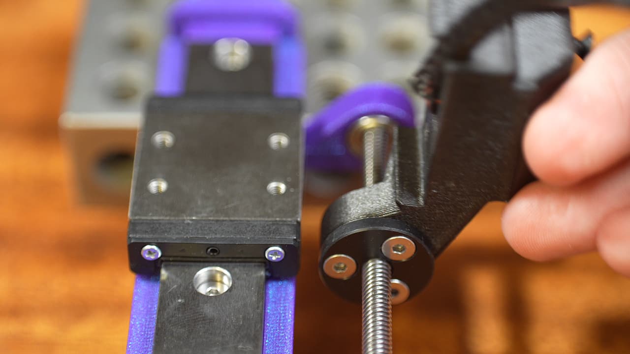
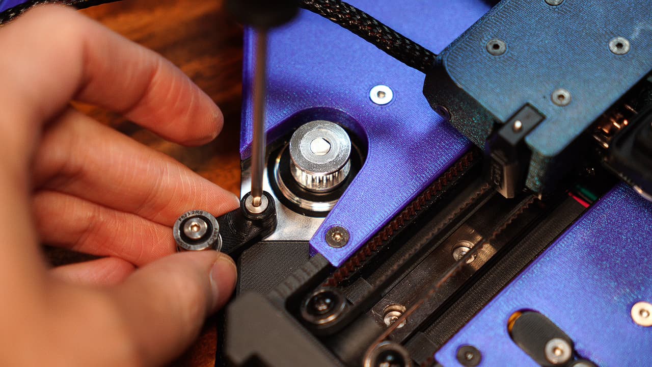
Tighten grub screws
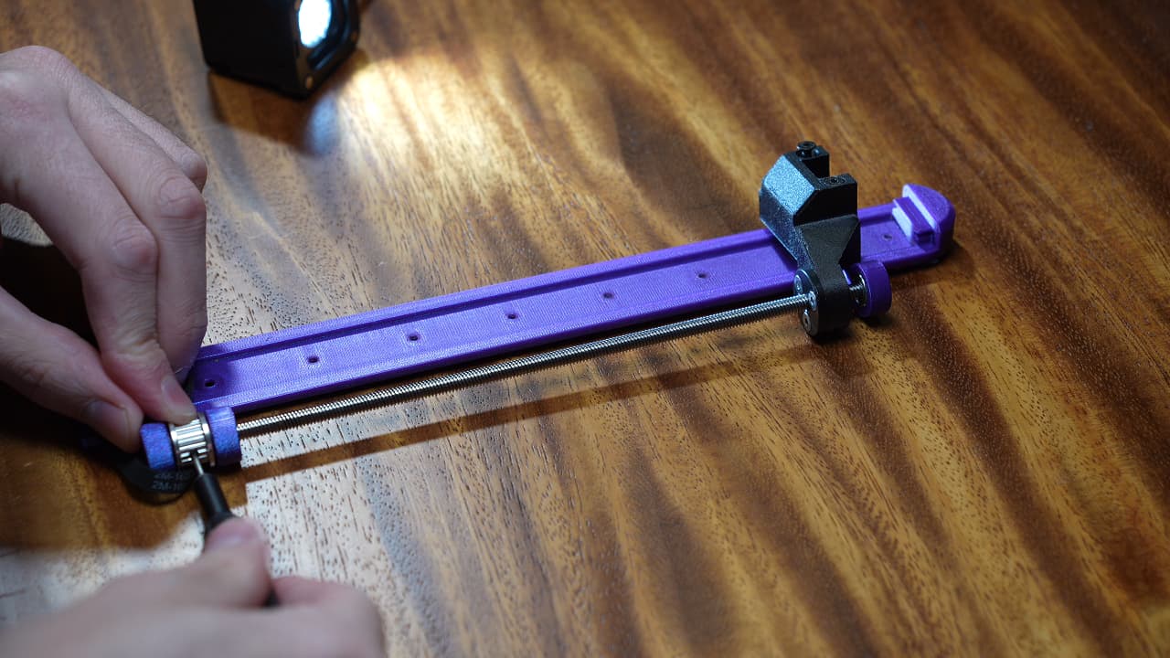 Tighten the grub screws using a 1.5mm allen key.
 -
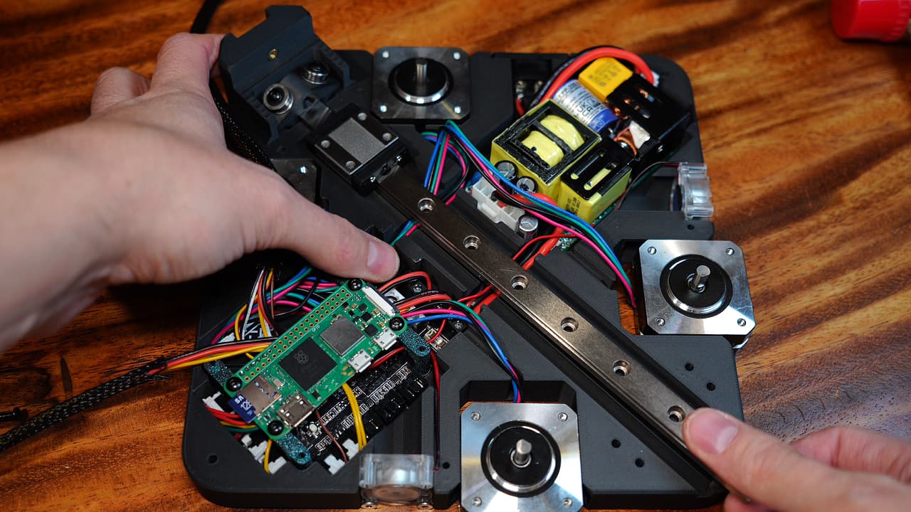
Install the rail & spacers
 Lay down the rail, then starting at the top hole, add 3d printed spacers to the first 3 holes, omit the 4th if you want to use the spool holder, and then proceed to add the last 3 spacers. Leave the bottom two holes empty to use to mount the Z-axis to the chassis.
 -
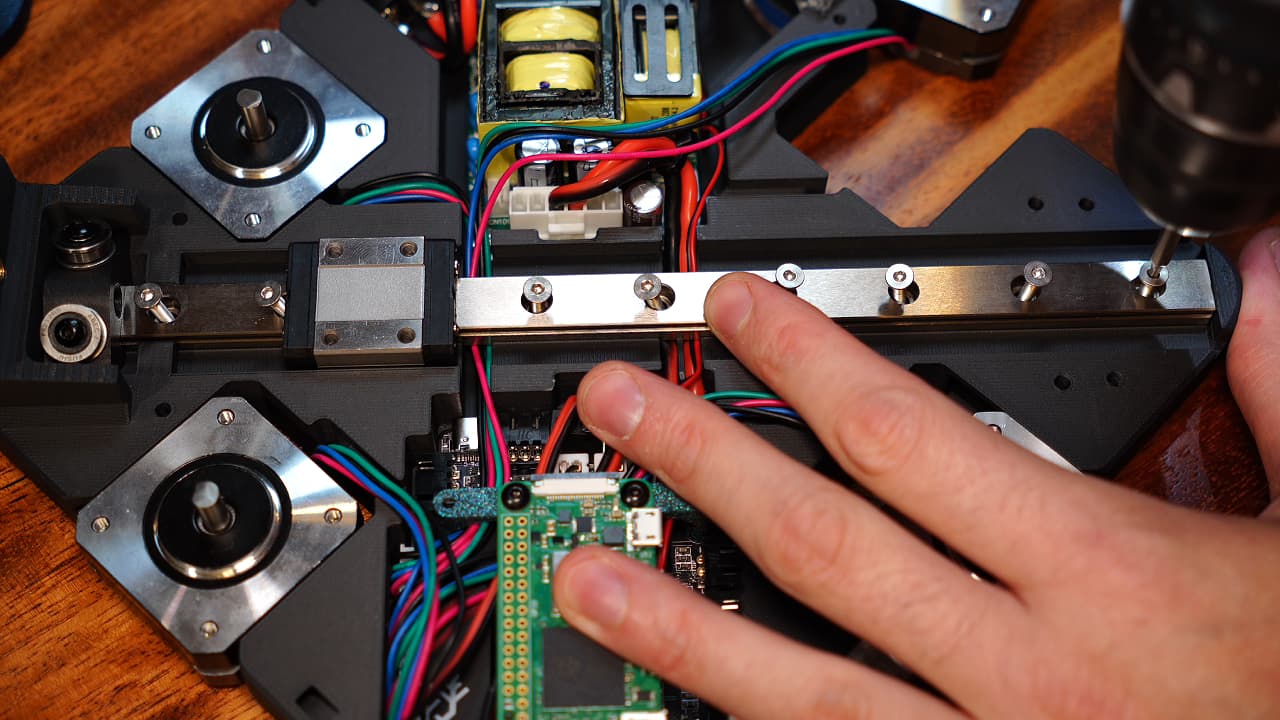
Screw in the rail
 Fasten the rail with screws in the holes that you added spacers to.
M38mm
Fasten the rail with screws in the holes that you added spacers to.
M38mm -
Gather edge connector parts
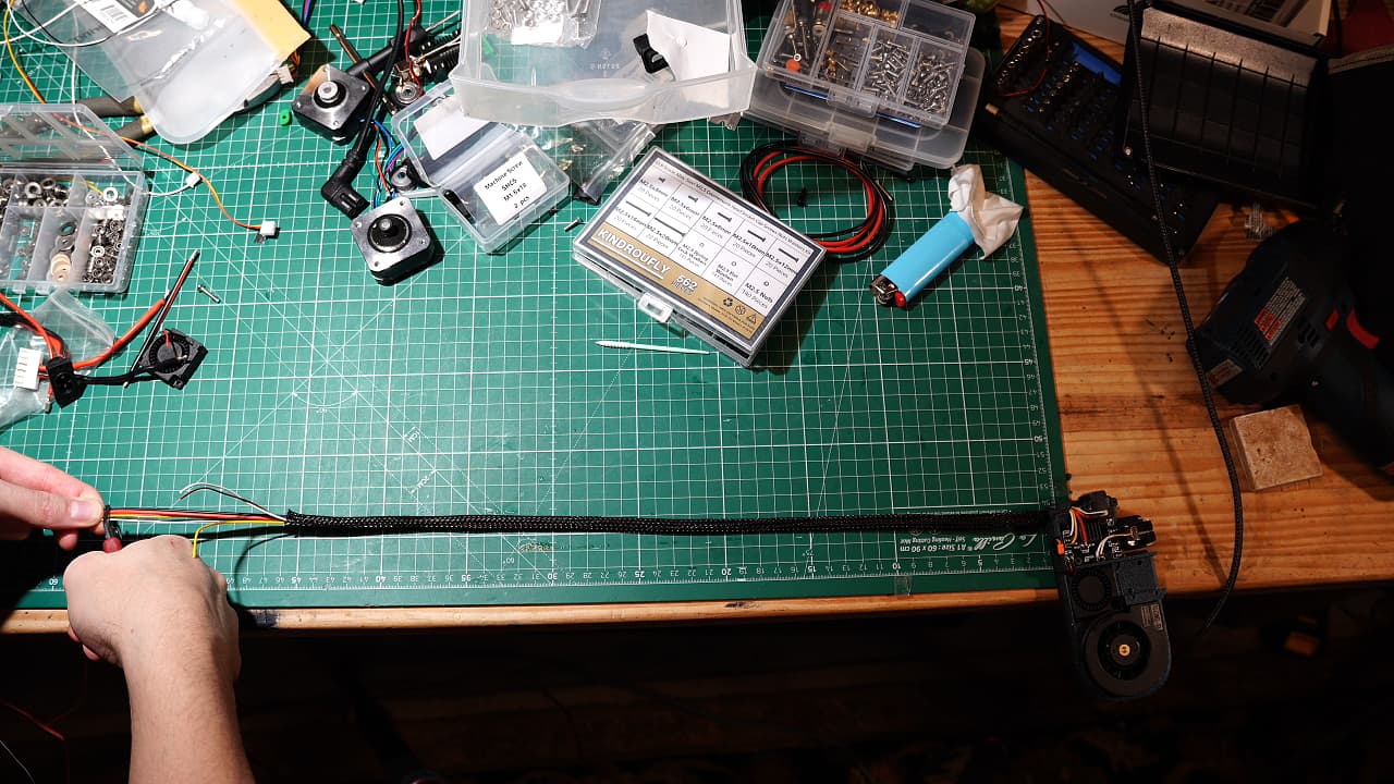
 Cut approximately 50cm of silicone power wire and signal wires.
 -
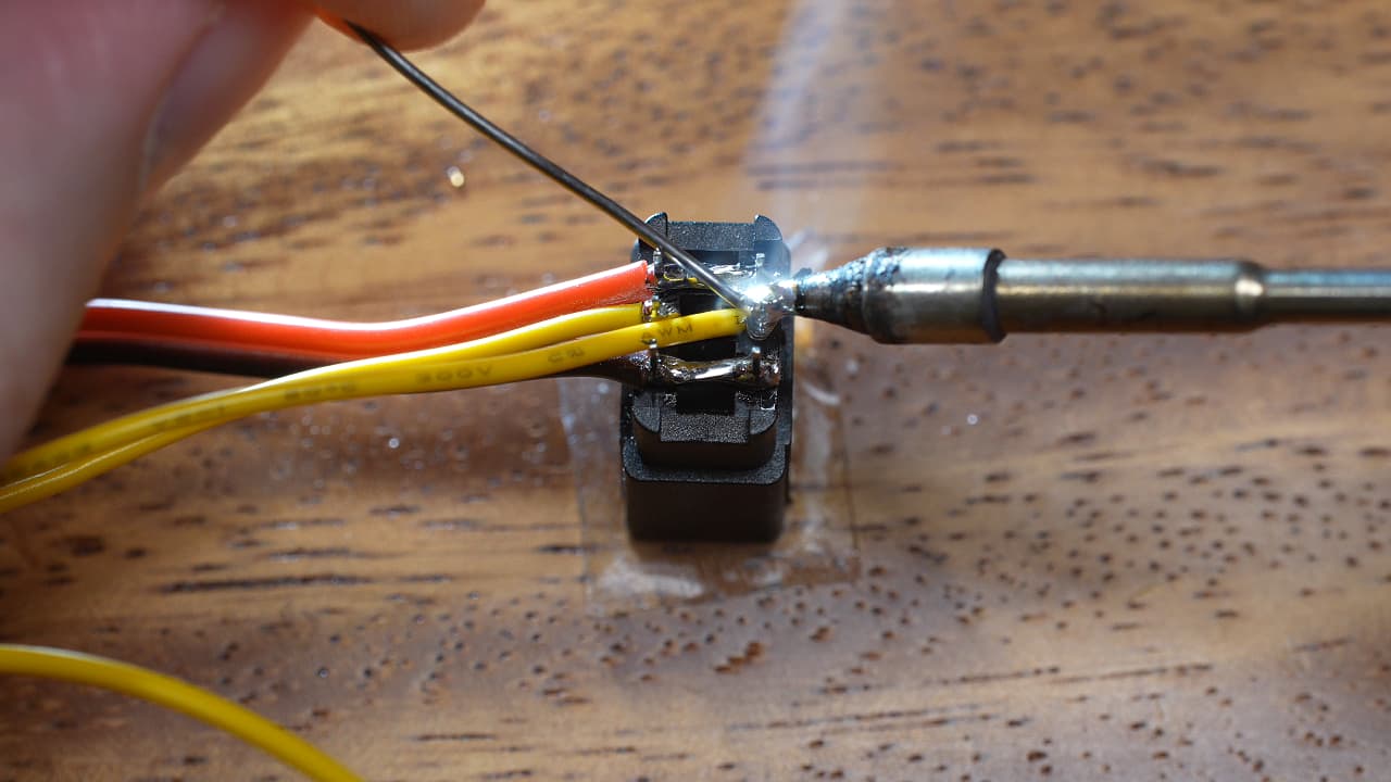
Solder the power wires
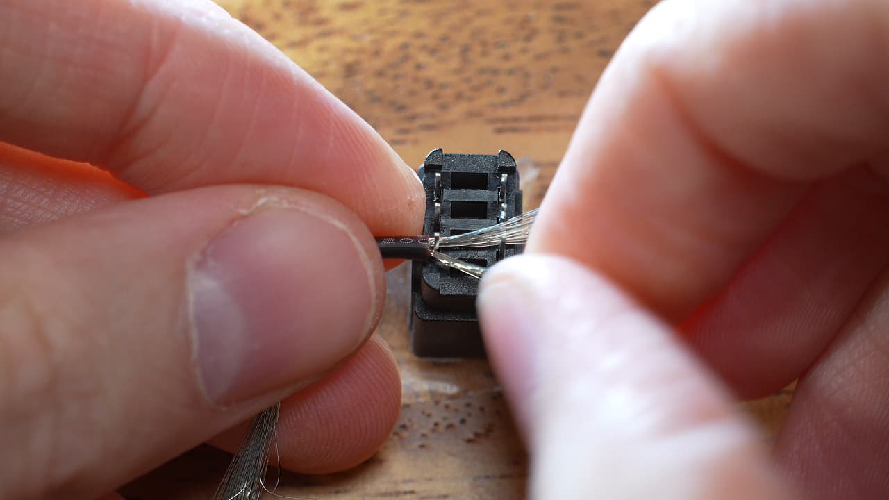 Fan out the wire strands, and use the wire to bridge the two conductors as shown. Twist the end. Solder. Trim the excess.
 -
Solder the signal wires
 Solder two thin gauge signal wires to the two middle conductors.
 -
Sleeve the wires
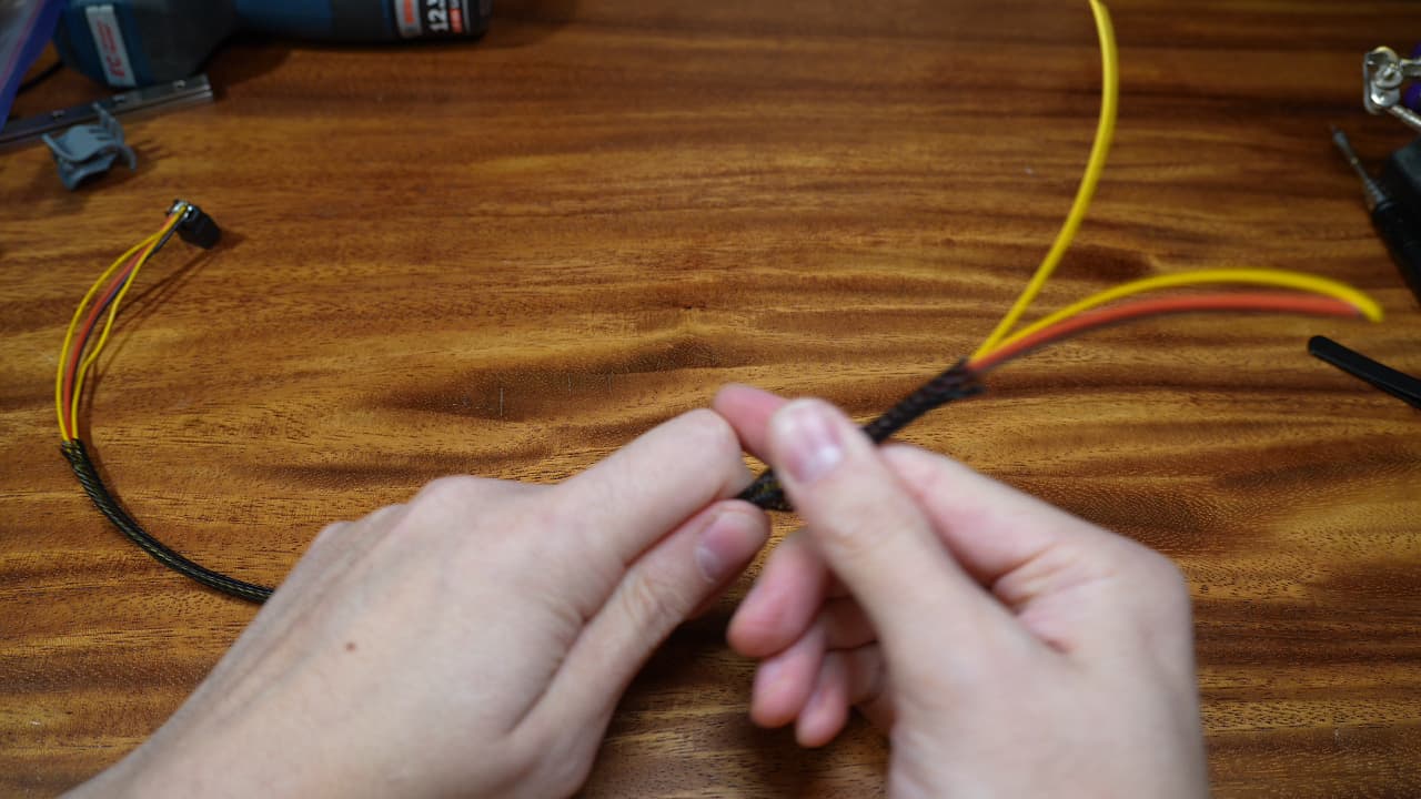 Cut the wire sleeve to 32cm and finesse it onto the wires.
 -
Cut the wires
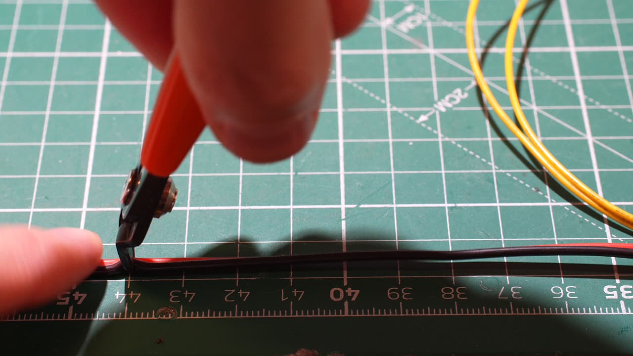 Cut the power wire to 44cm and the signal wires to 42cm.
 -
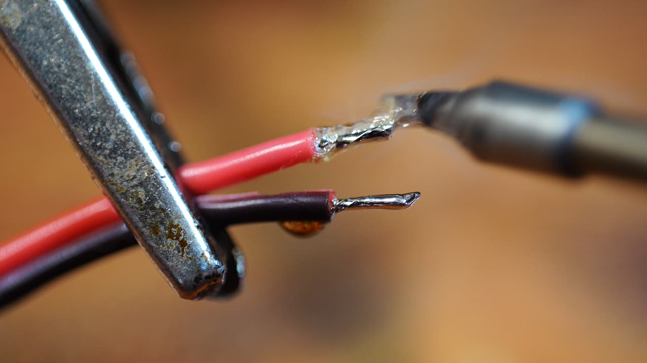
Tin the power wires
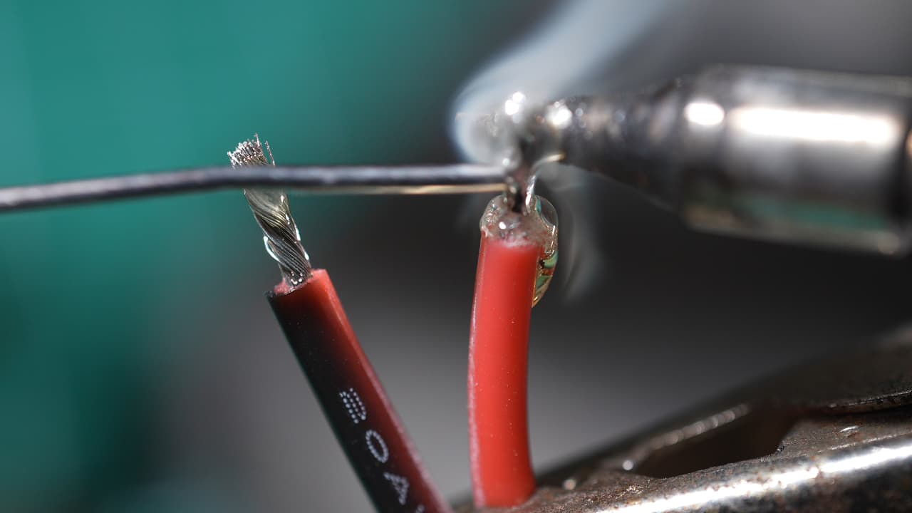 Strip 5mm of insulation from the power wires and tin them.
 -
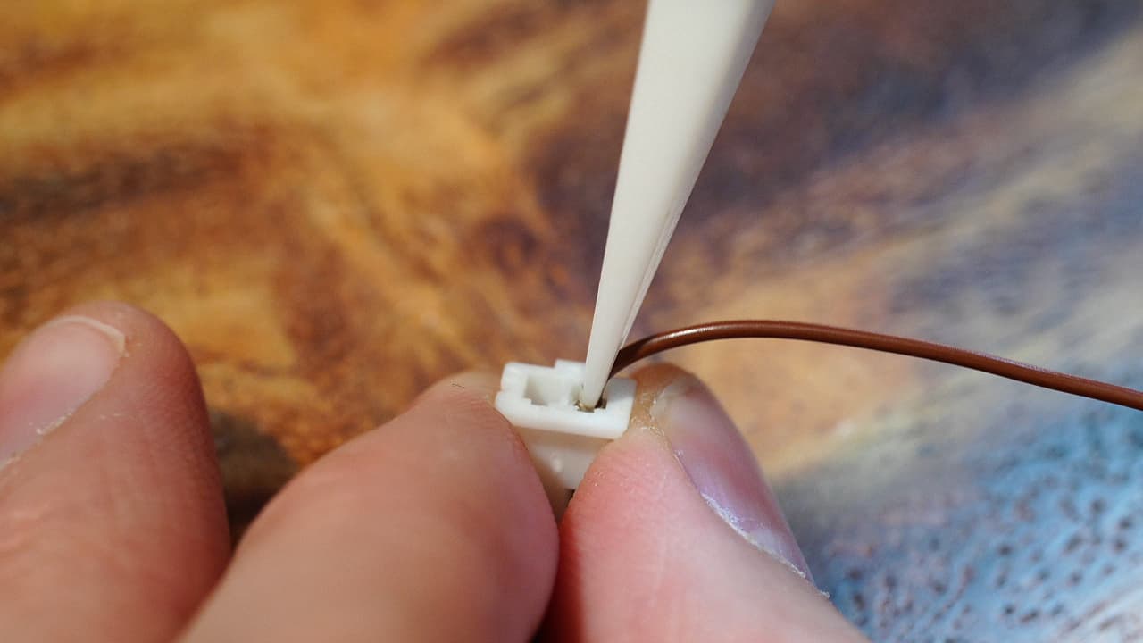
Crimp signal wires
 Crimp the two signal wires. Learn how to crimp goooood here.
 -
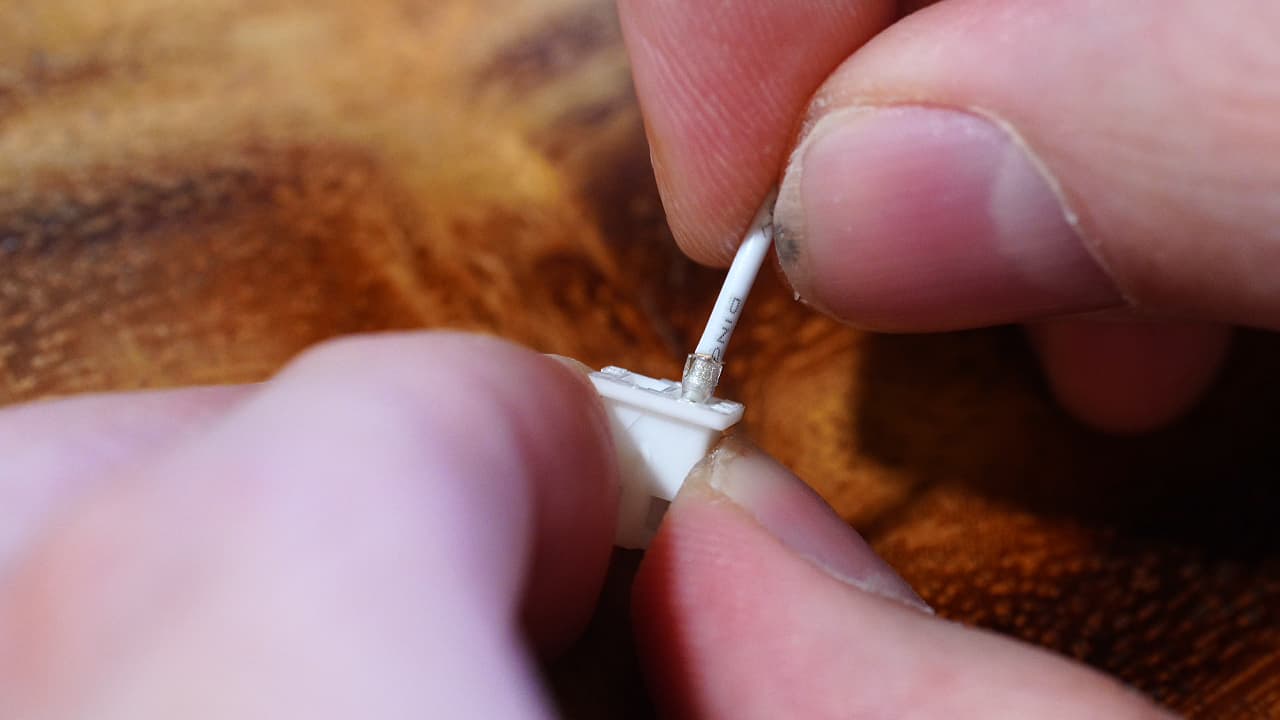
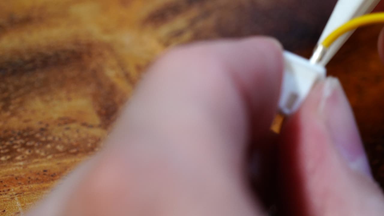
Insert connector
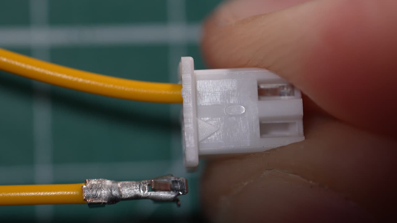 Insert the two crimped signal wires into the JST connector. Polarity does not matter.
 -
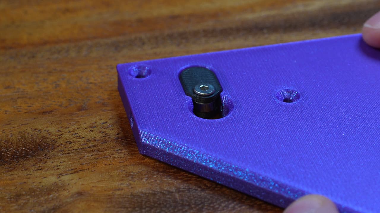
Slide in edge connector wire
 Slide the wires in through the slot in the bracket and press the edge connector into place.
 -
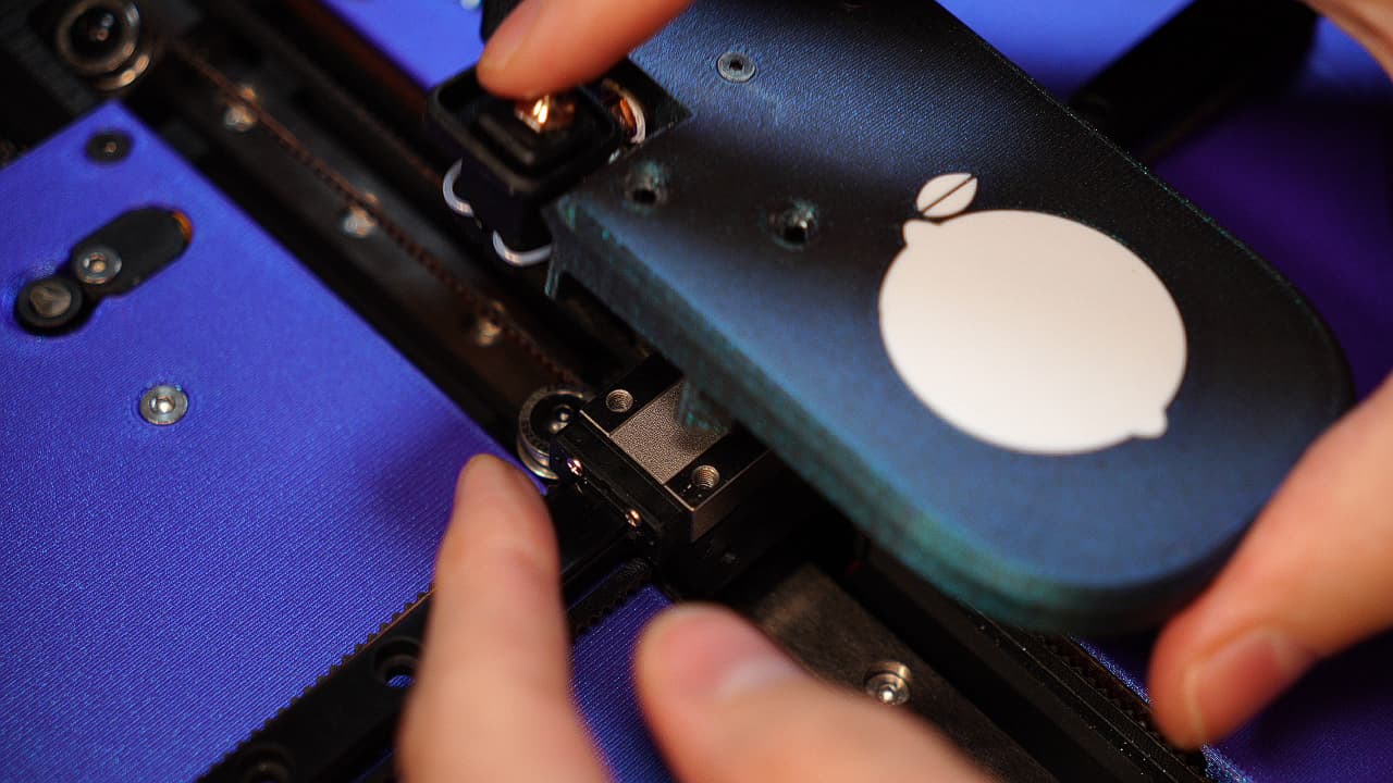
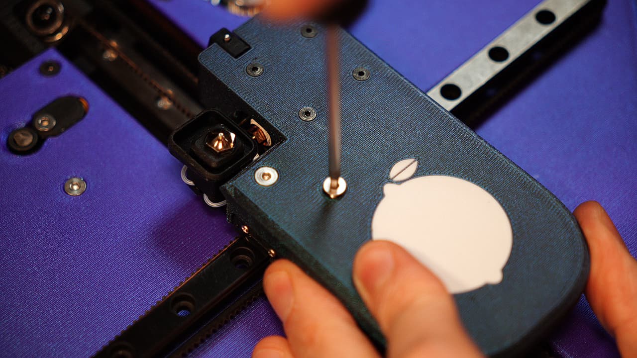
Tighten bracket
 Tighten the bracket on to the carriage with two screws.
 M325mmPicture shows button head screws.
 -
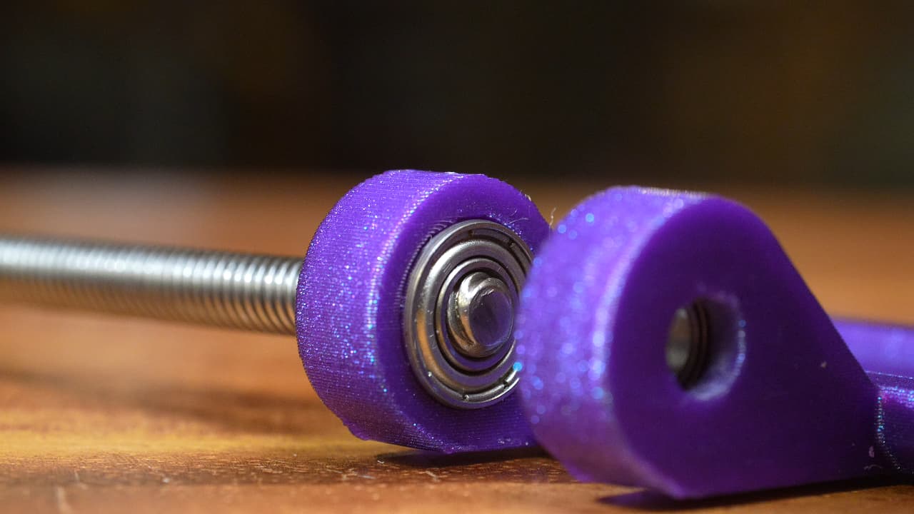
Gather Lemonstruder parts
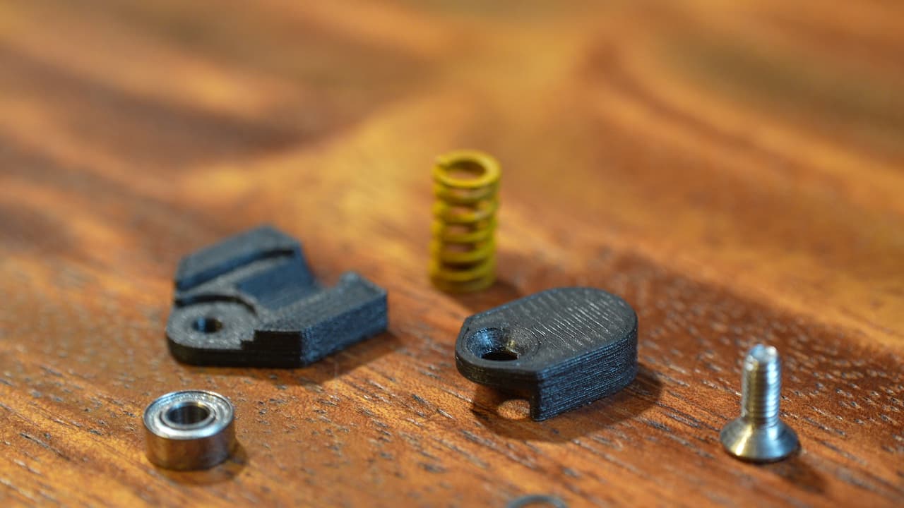 Printed top & bottom halves, yellow spring, 8mm countersunk screw, small bearing, 2 small shims, and super glue.
 -
Glue halves together
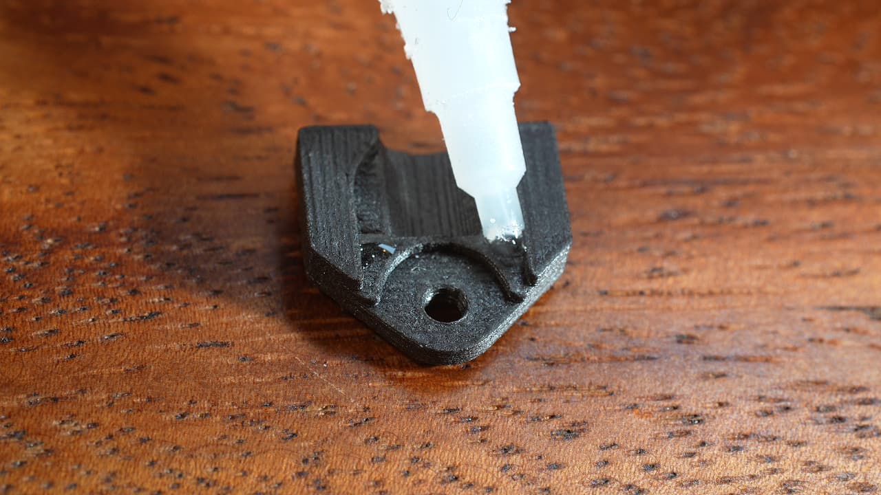 Dap two tiny dots of super glue as pictured.
 -
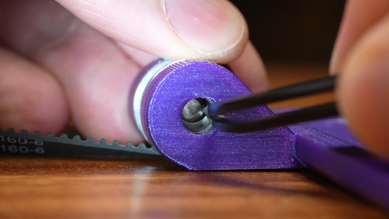
Insert the first shim
 Insert the first shim, using a small screw to help guide it in. This shim will allow the bearing to rotate against the plastic housing.
 -
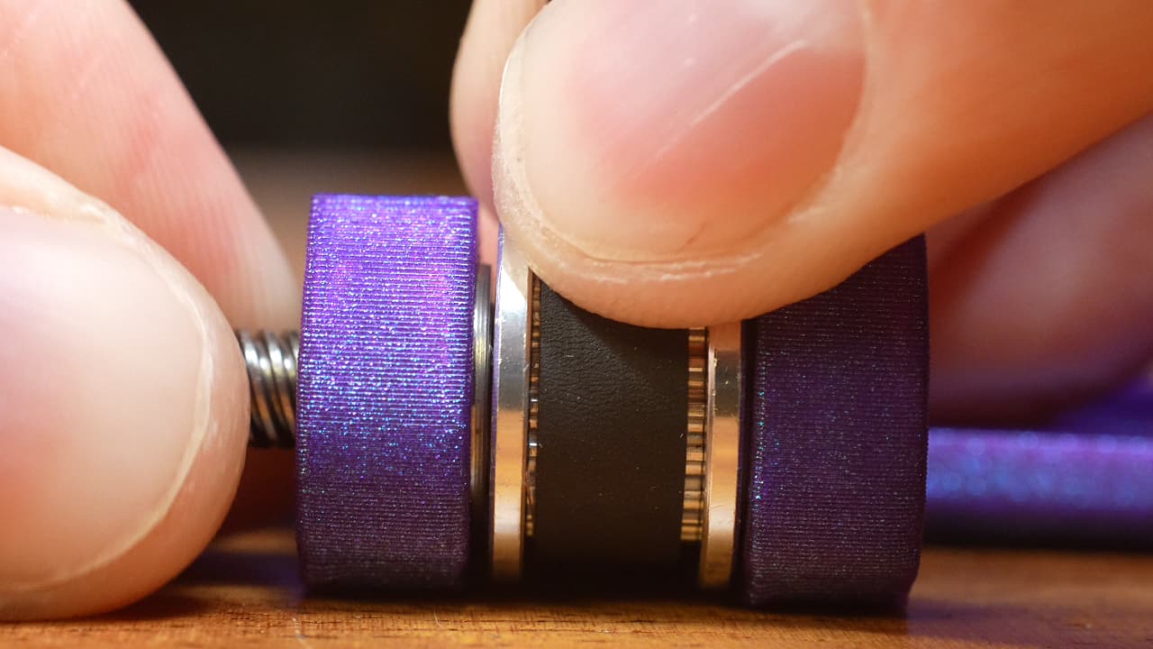
Insert the bearing
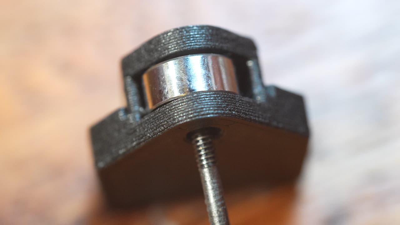 Insert the bearing on top of the shim.
 -
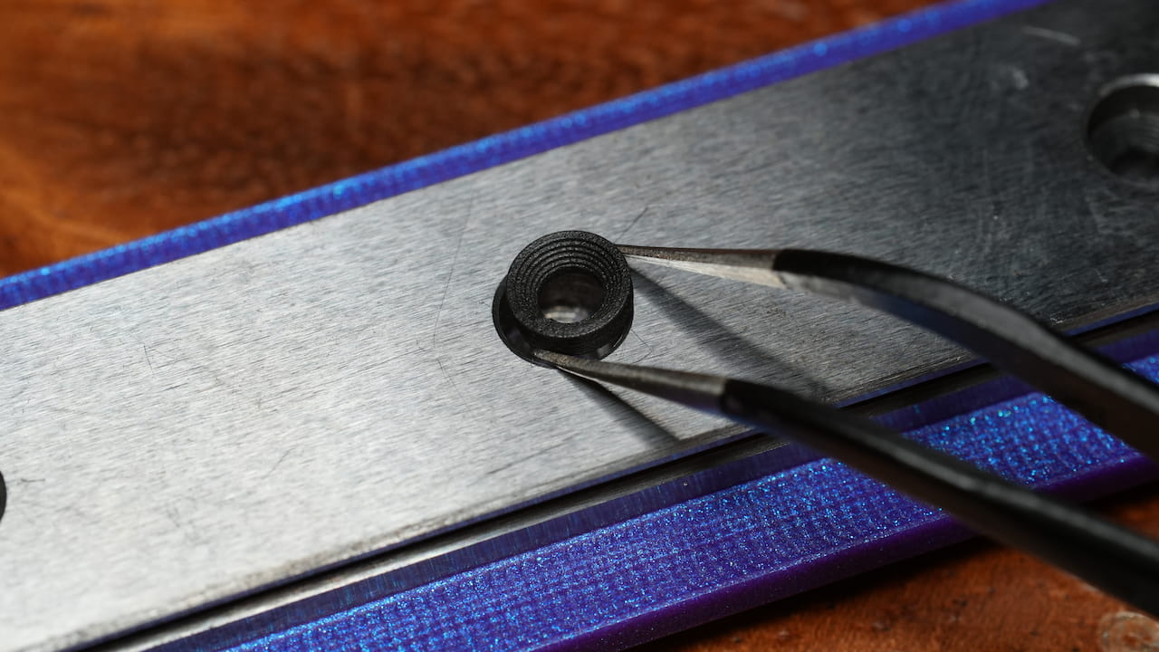
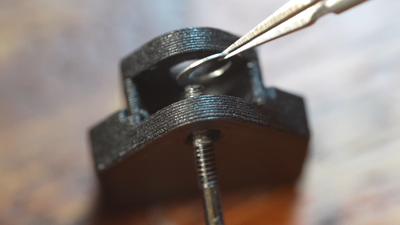
Insert the second shim
 Using tweezers, insert the second shim between the bearing and the plastic housing.
 -
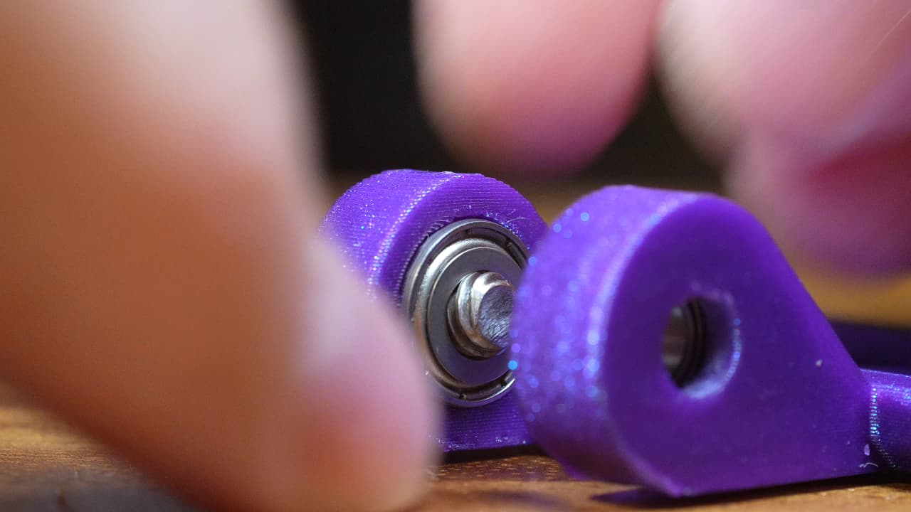
Insert the screw
 Insert the screw, pushing out the small screw. This screw is designed to not fit completely flush.
M38mm
Insert the screw, pushing out the small screw. This screw is designed to not fit completely flush.
M38mm -
Insert the spring
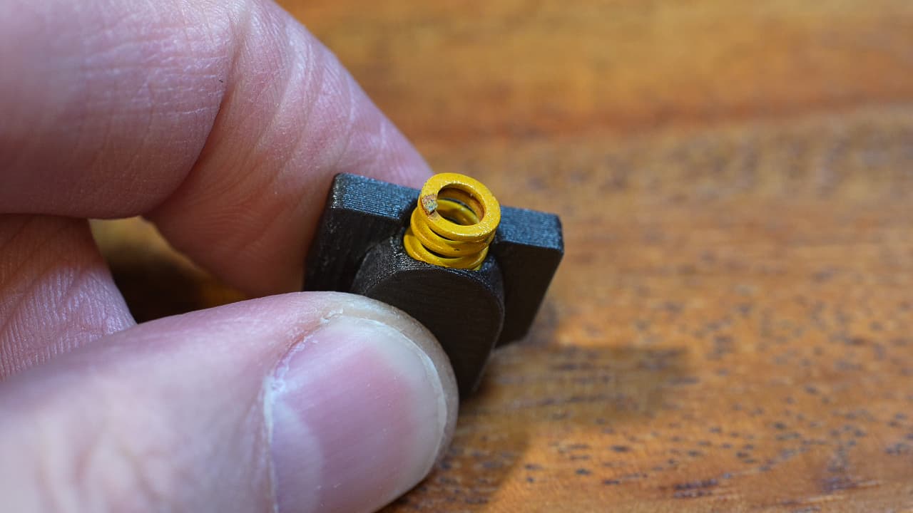 Insert the unmodified yellow boinger.
 -
Insert the Lemonstruder
 Insert the Lemonstruder into the left top plate.
 -
Cut motor wires
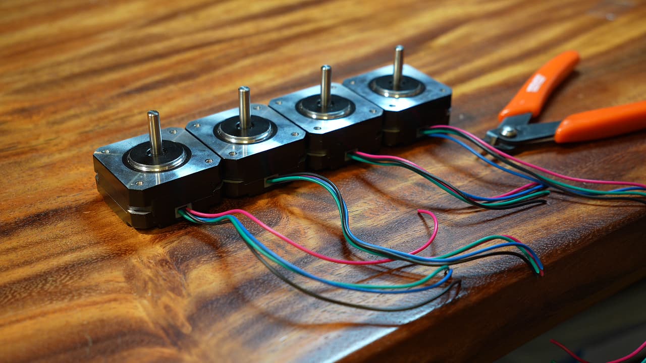 Cut the motor wires to the lengths 15cm, 15cm, 10cm, 23cm.
 -
Crimp motor wires
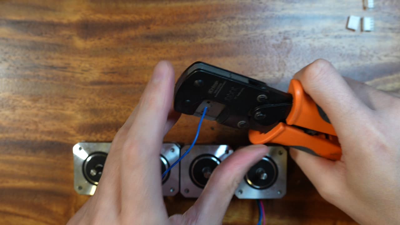 Crimp every motor wire.
 -
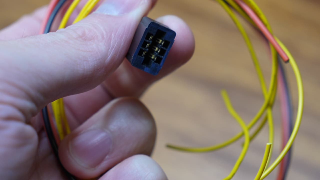
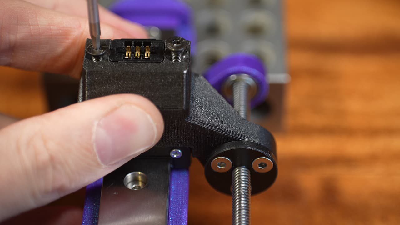
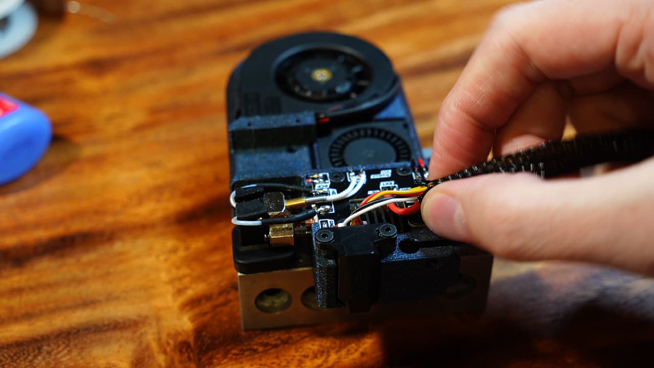
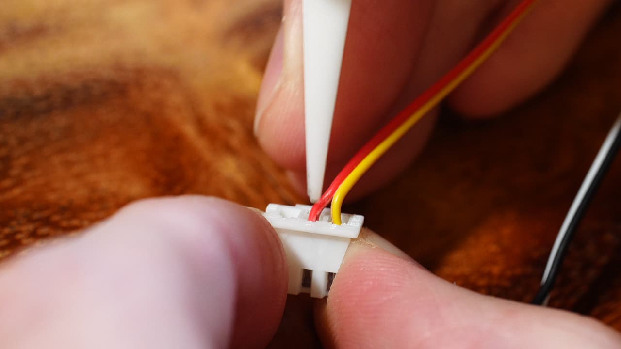
Insert the crimps into the connector
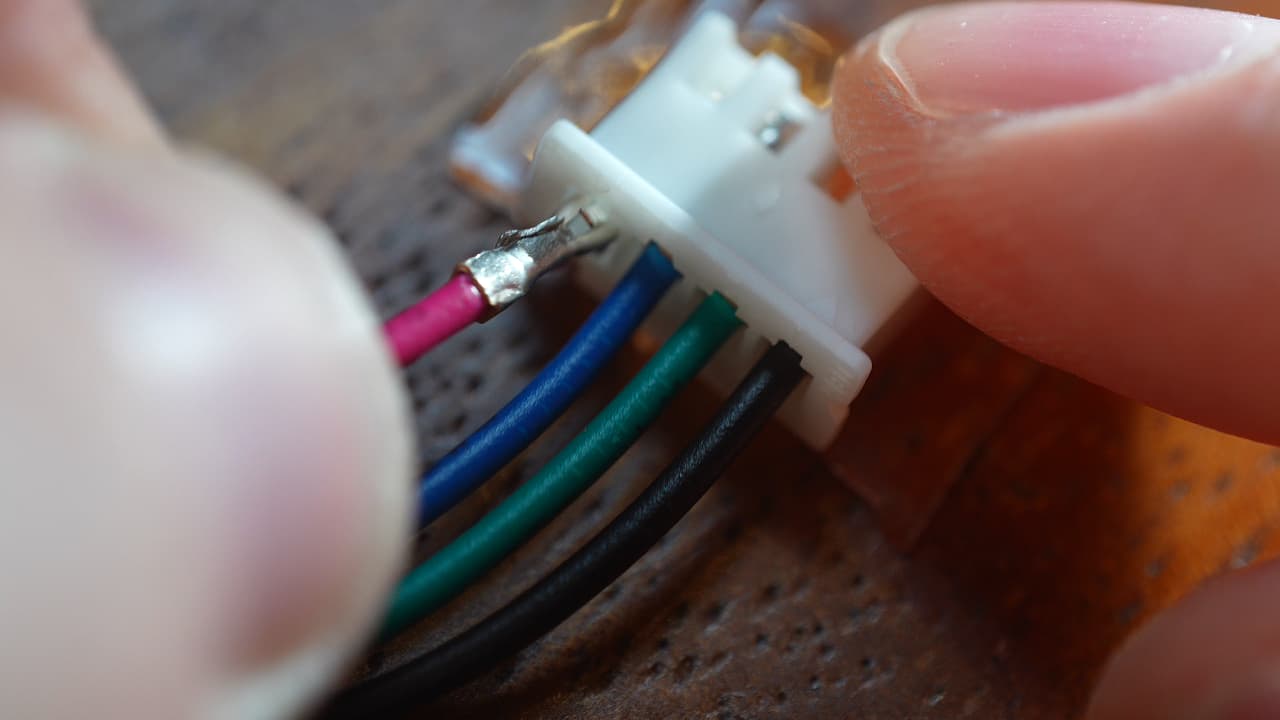 Starting from the triangle mark, go in order of black, green, blue, red.
 -
Gather parts for the tool
 Tool body (printed), hotend, small fan, big fan, probe, connectors, crimps, power wires (silicone), signal wires, M2.5 x 6mm screws, pcb.
 -
Tighten the heat break
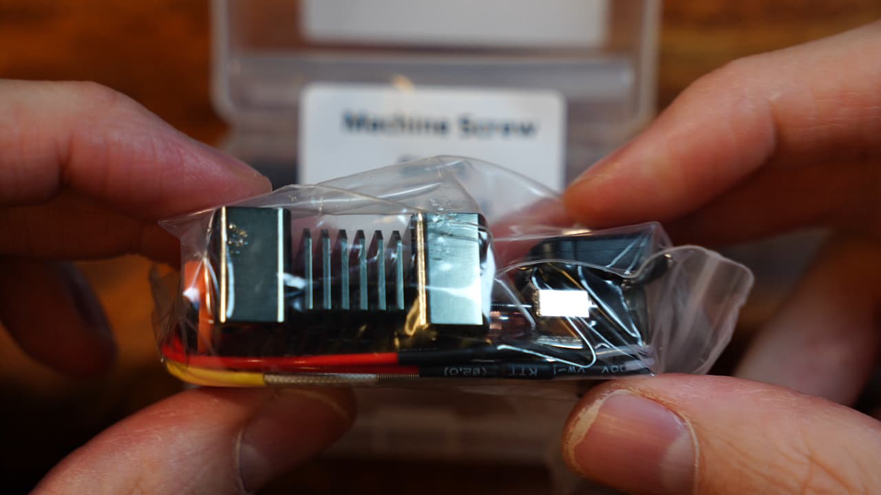 The heat break is loose from the factory. You need to rebuild the hotend.
 -
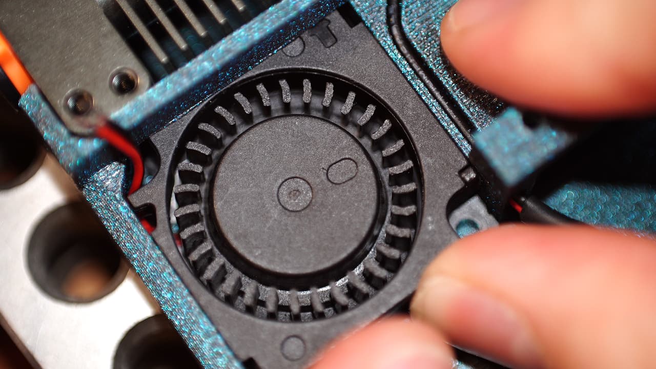
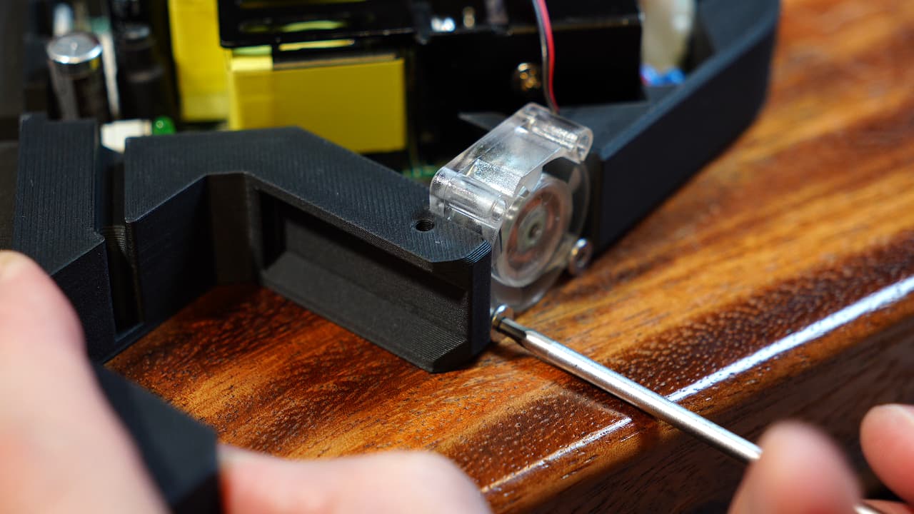
Modify the part cooling fan
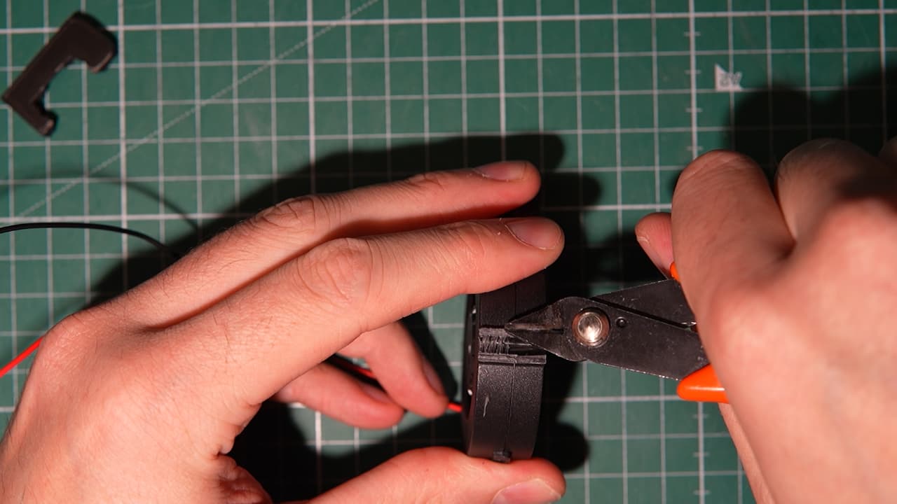 Completely remove the two mounting tabs and wire retaining clip.
 -
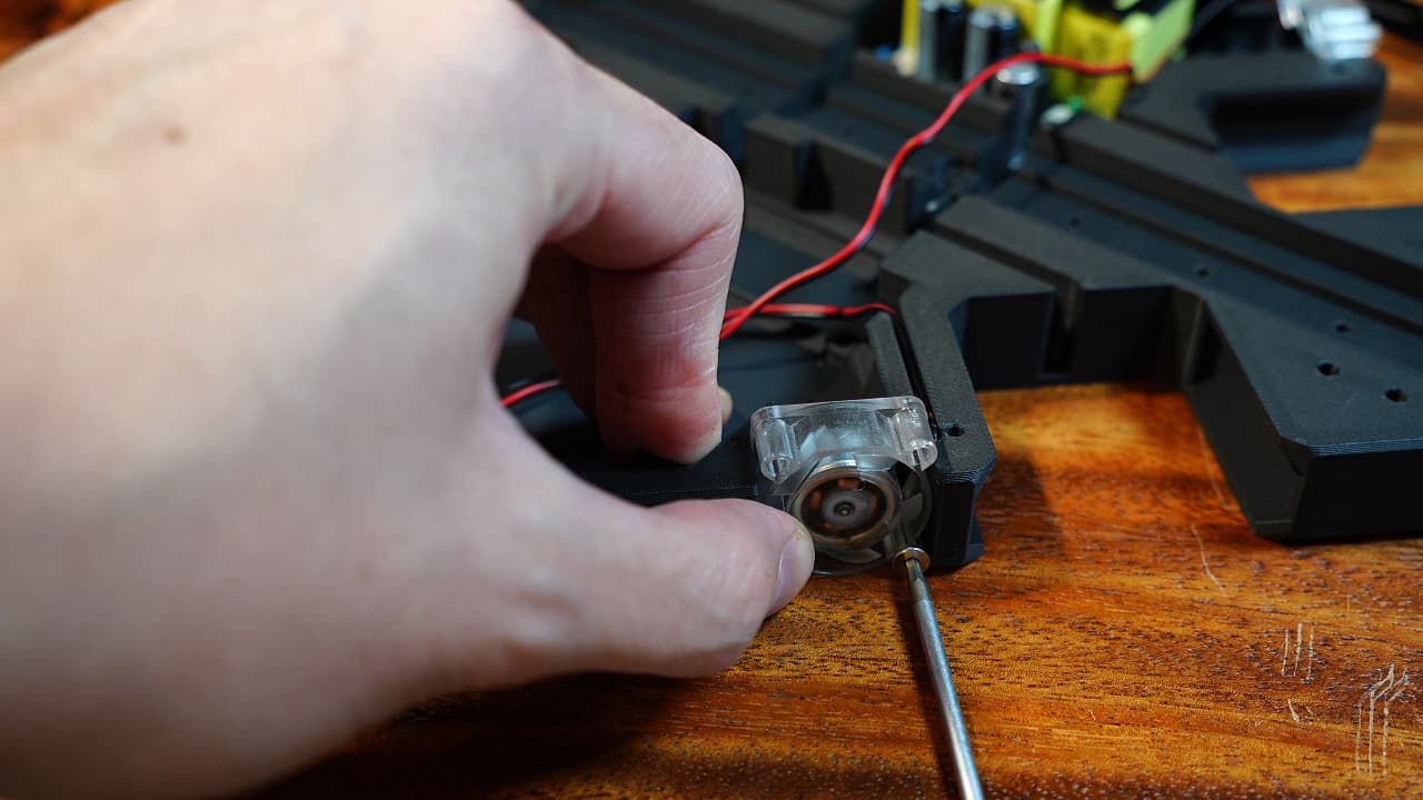
Push the wires through
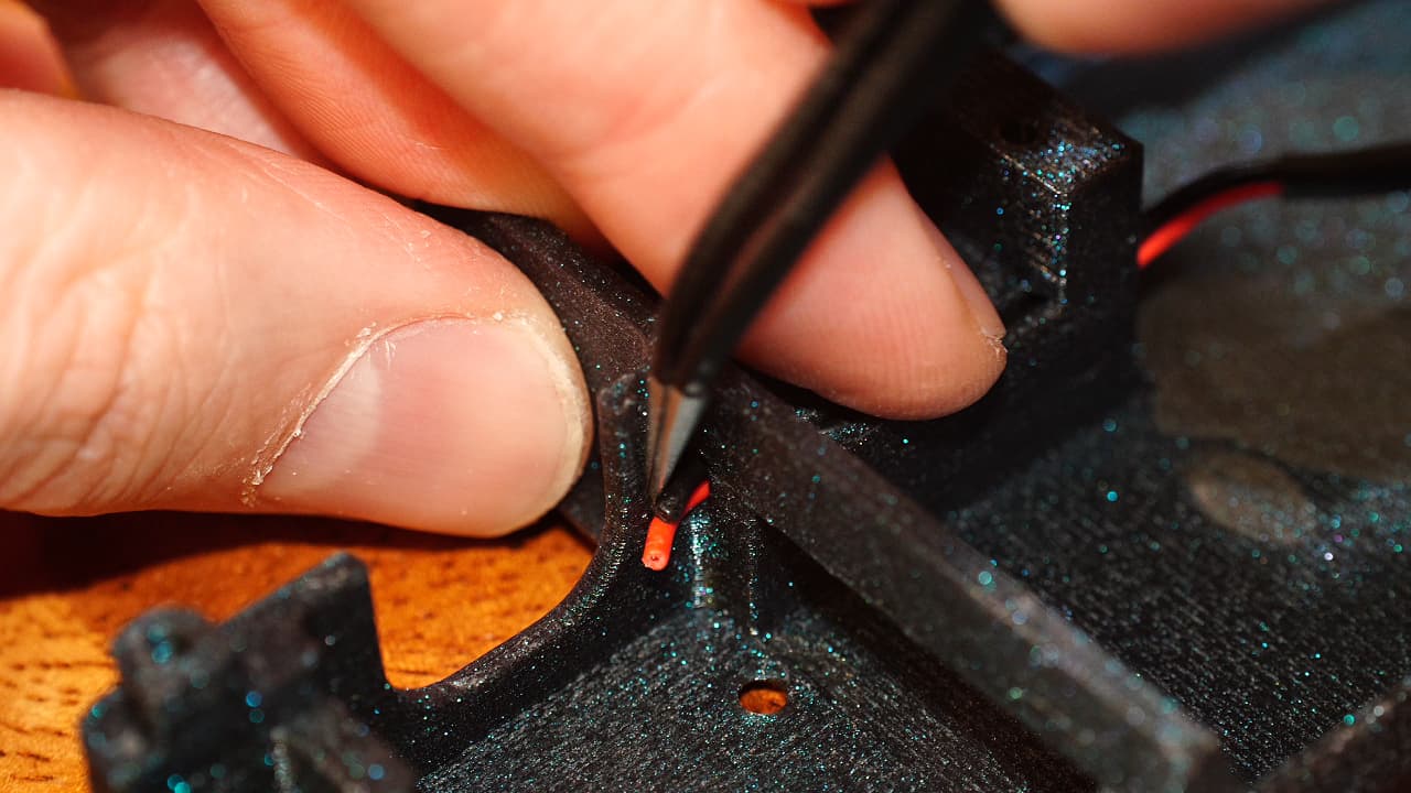 Push the part cooling fan wires through the cavity of the tool head.
 -
Drop in the hotend
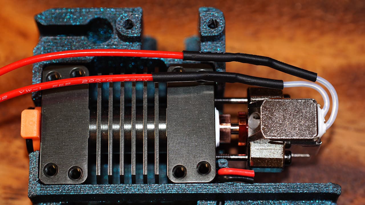 The hotend will smoosh the wires and keep them in place. Now is a good time to strip the wires.
 -
Fasten the hotend
 Fasten the hotend to the tool body.
M2.56mm
Fasten the hotend to the tool body.
M2.56mm -
Fasten the probe
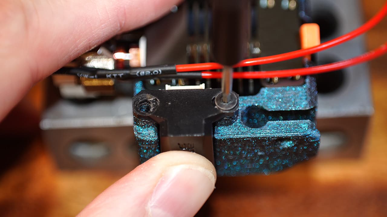 Fasten the probe to the tool body.
M2.56mm
Fasten the probe to the tool body.
M2.56mm -
Insert small fan
 Insert the small fan and push it under the ledge so that it's touching the head sink.
 -
Drop in the part cooling fan
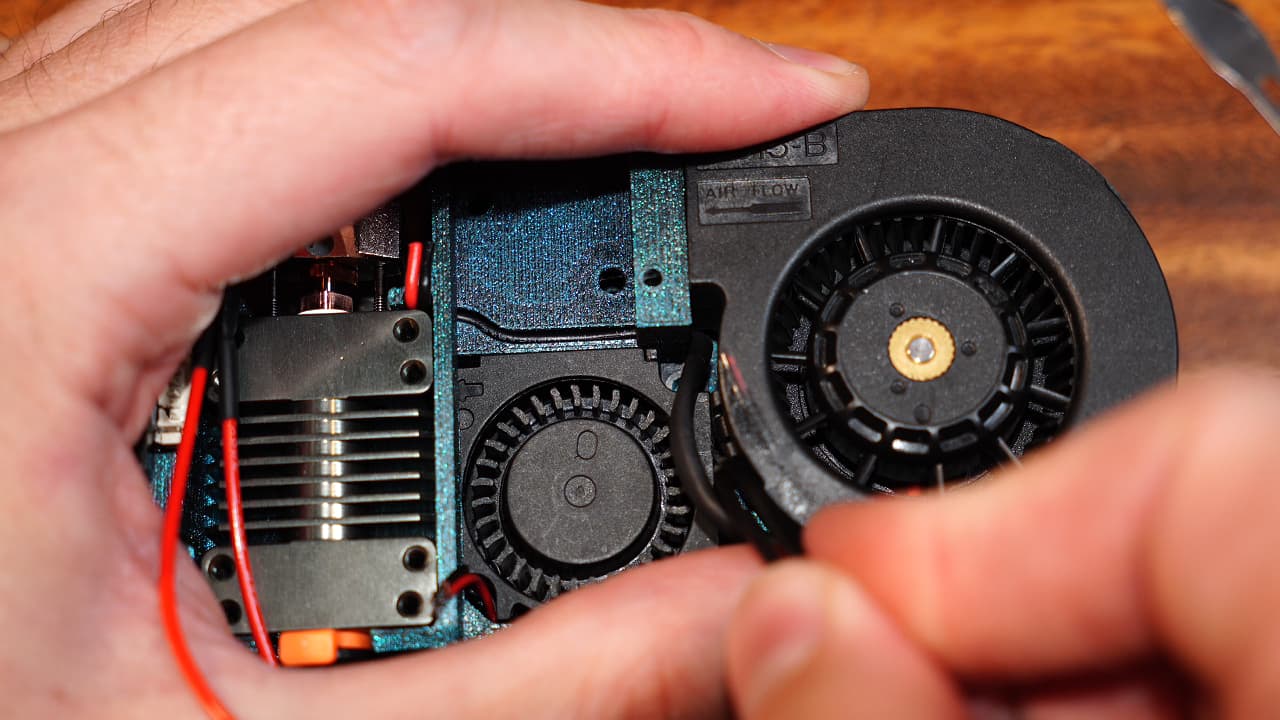 Finish dropping in the cooling fan to lock everything in place.
 -
Tin the pcb
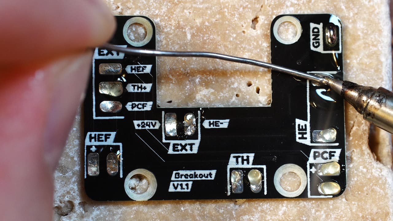 Apple some solder to hasten the wire bonding.
 -
Fasten the pcb
 Fasten the pcb to the heat sink.
M2.56mm
Fasten the pcb to the heat sink.
M2.56mm -
Solder the hotend fan
 Solder the hotend fan (small fan) to the pads on the pcb.
 -
Solder the part cooling fan
 Solder the part cooling fan (big fan) to the pads on the pcb.
 -
Solder the heater
 Clip and strip the wires at the end of the heat shrink tube. Solder to the pads on the pcb.
 -
Shorten the thermistor spring
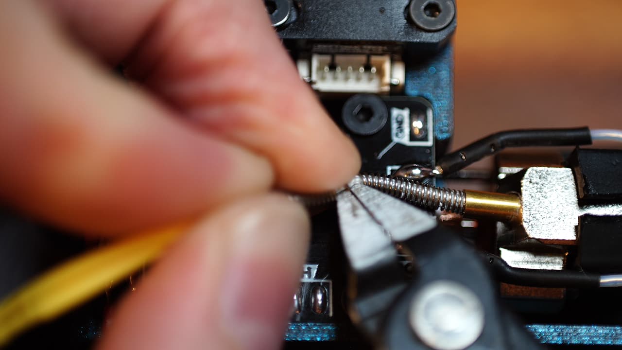 Clip the spring in half.
 -
Solder the thermistor
 Clip and strip the wires and solder them to the pads on the pcb.
 -
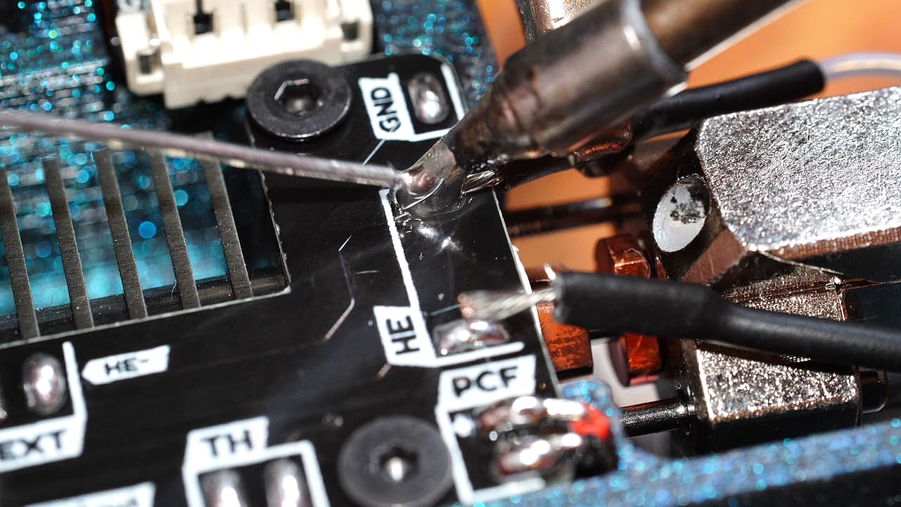
Plug in & solder the probe
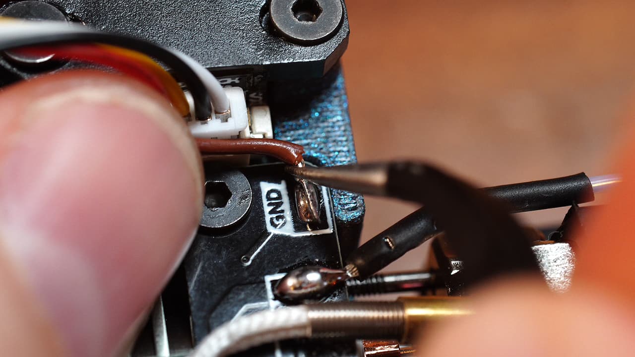 Plug in the probe and split off one of the grounds (black or brown) and solder it to the pad. You can reuse this wire so don't throw it away.
 -
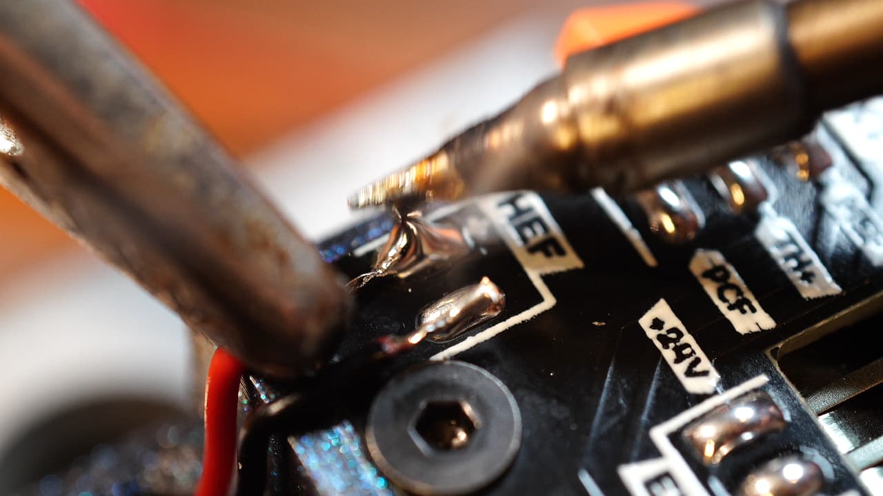
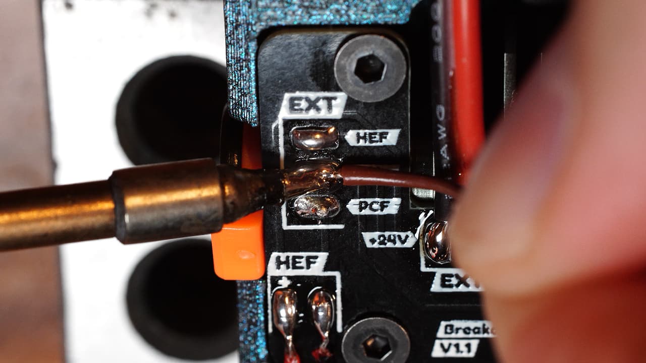
Solder the heater wire
 Solder the heater wire. Don't solder it as pictured. The pcb is literally labelled, I don't know why I flipped it but I did. I will replace this picture later.
 -
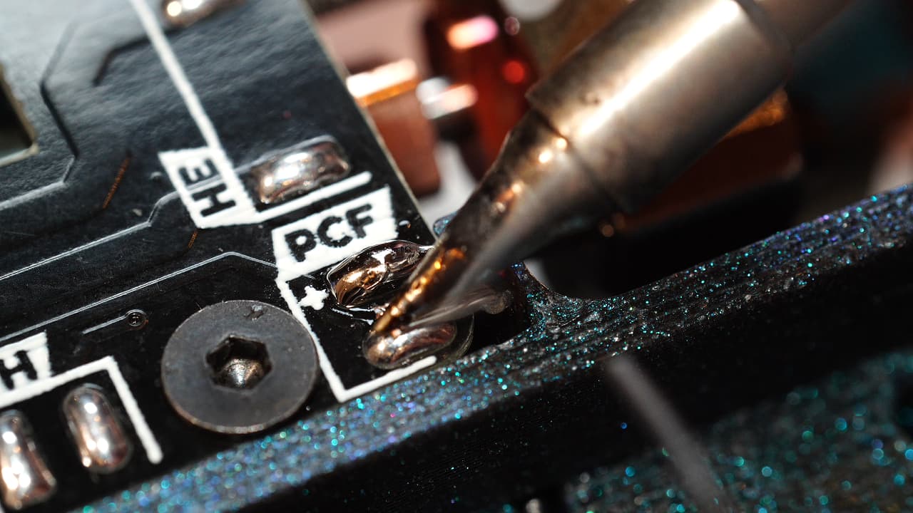
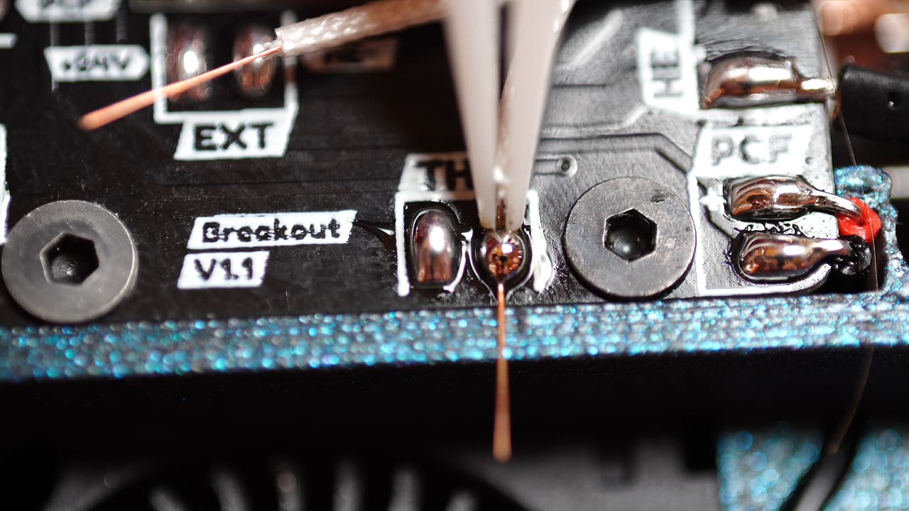
Solder the thermistor wire
 Using the leftover wire from the probe, solder the thermistor signal wire.
 -
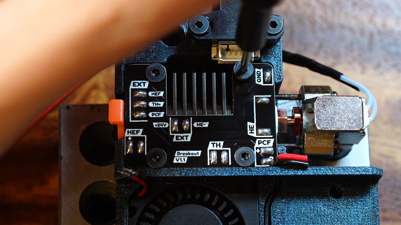
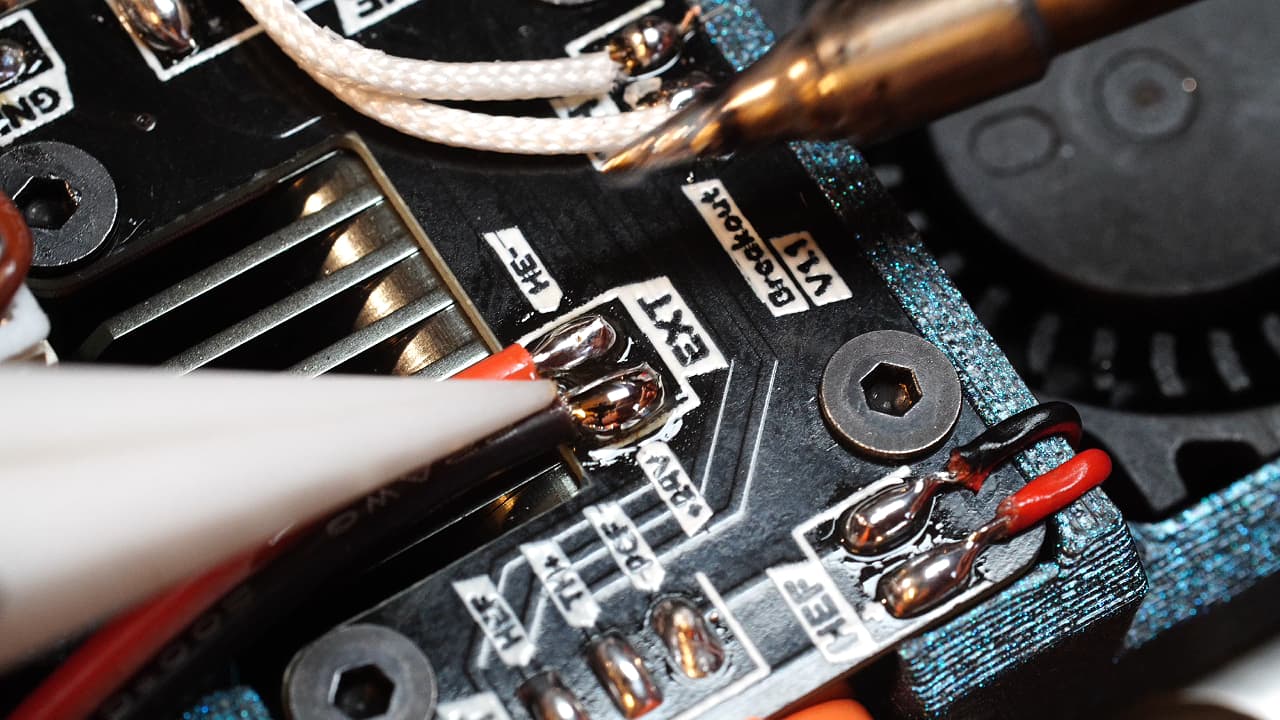
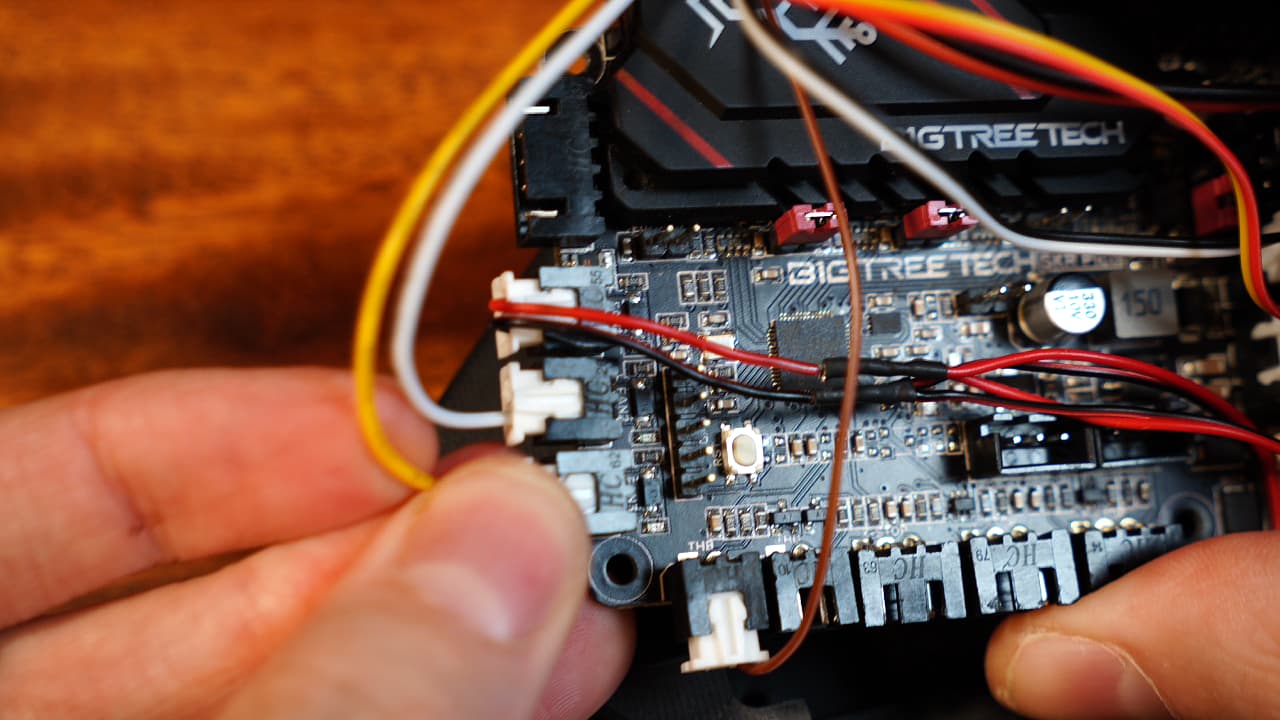
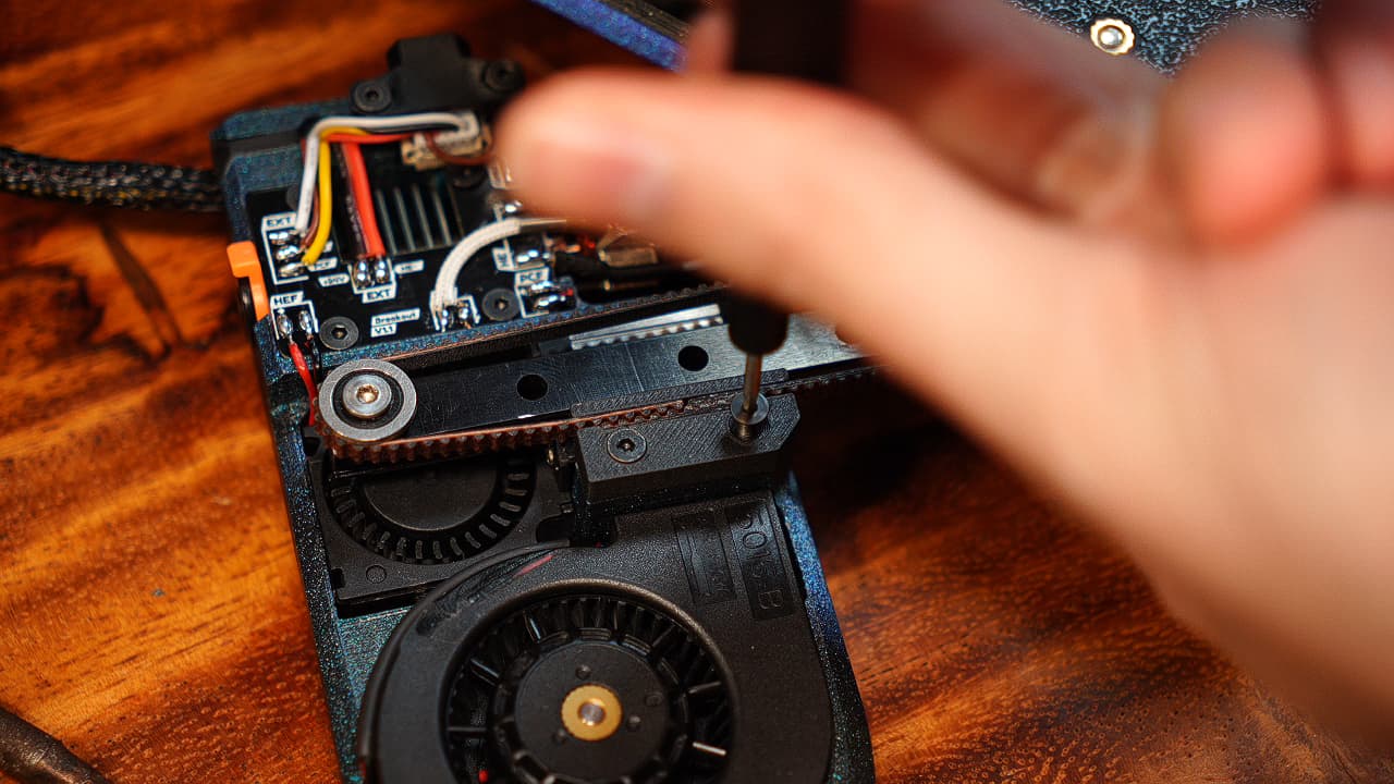
Solder the fan wires
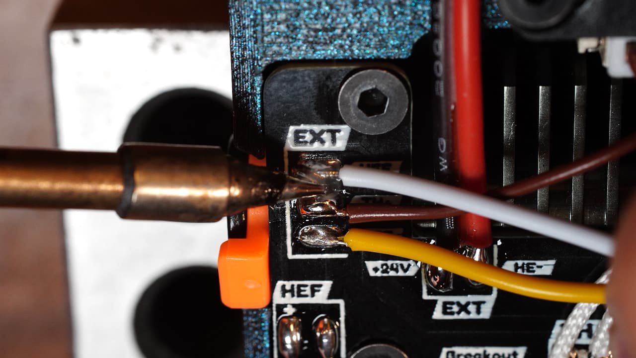 Cut two wires roughly to 50cm and solder them to the two fan pads on the pcb.On the pcb, the silk screen has a mistake. The HEF and PCF labels are swapped. From top to bottom, the correct wiring is PCF, TH+ and HEF.
 -
Wrap the wires
 Use 47cm of wire sleeve to wrap the wires.
 -
Insert the clamp
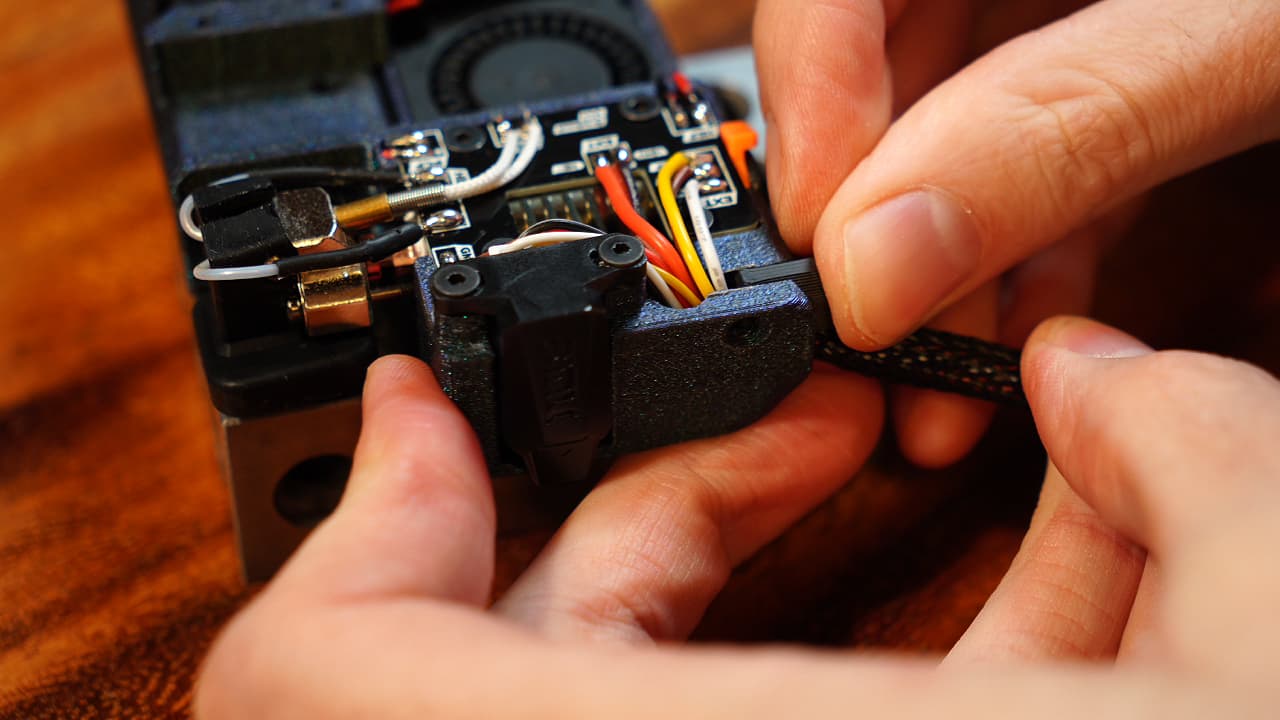 Clamp down the wires by pushing in the clamp and securing it with a screw.
M312mm
Clamp down the wires by pushing in the clamp and securing it with a screw.
M312mm -
Clip the tool wires
 Cut the heater wire and probe wires to 53cm, the rest to 55cm.
 -
Tin the heater wires
 Trim back 5mm off the heater wires and tin the ends.
 -
Crimp the thermistor wire
 Crimp the thermistor wire and insert it into the connector side without the marking.
 -
Crimp the hotend fan wire
 Crimp the hotend fan wire and insert it into the connector side without the marking.
 -
Crimp the part cooling fan wire
 Crimp the part cooling fan wire and insert it into the connector side without the marking.
 -
Crimp the probe sensor wires
 Crimp the probe sensor wires and insert them into position 2 & 3 as shown.
 -
Crimp the probe servo wires
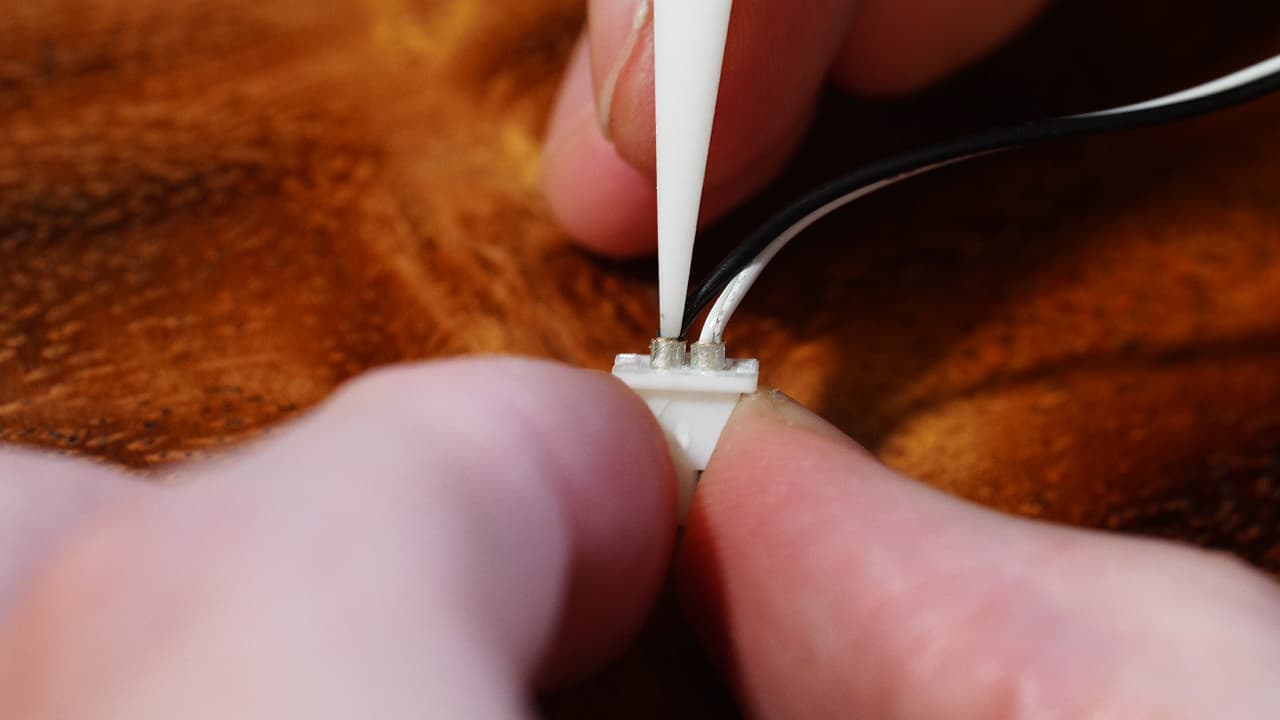 Crimp the probe servo wires and insert them as shown; black on the marking, white on the other position.
 -
Gather the chassis parts
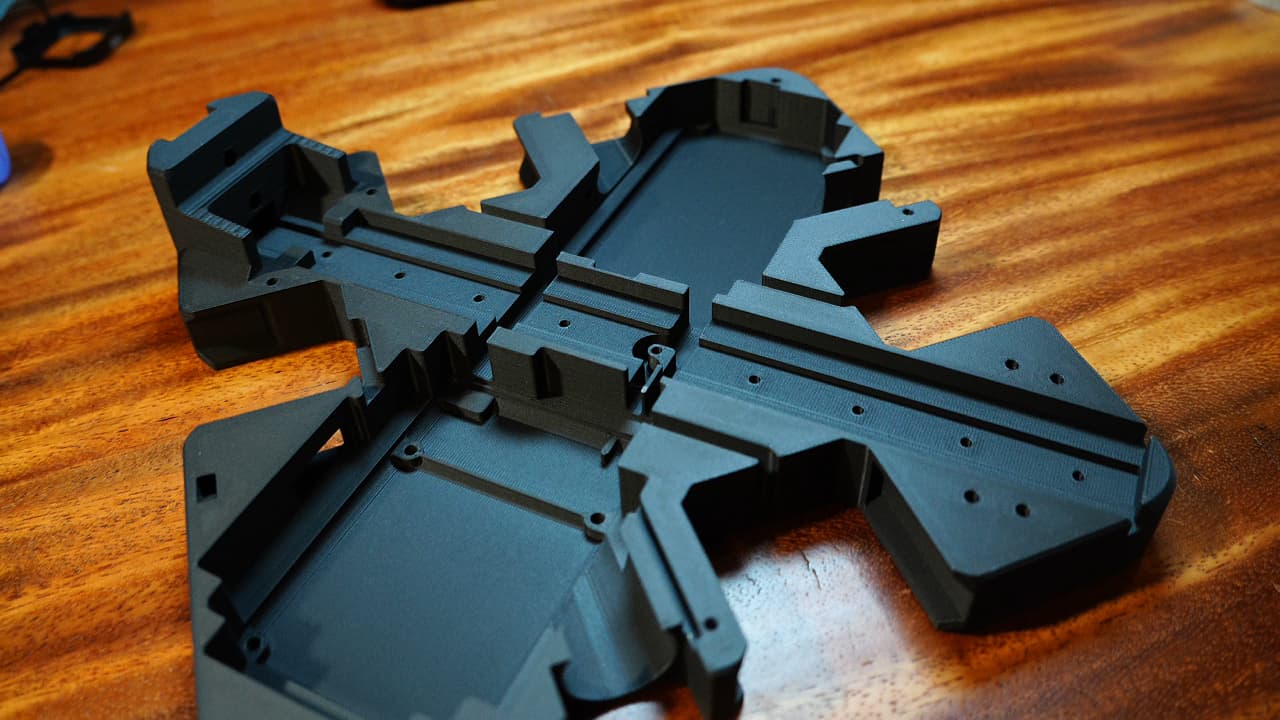 This is the rest of the parts! Draw the rest of the horse!
 -
Insert the heat set inserts
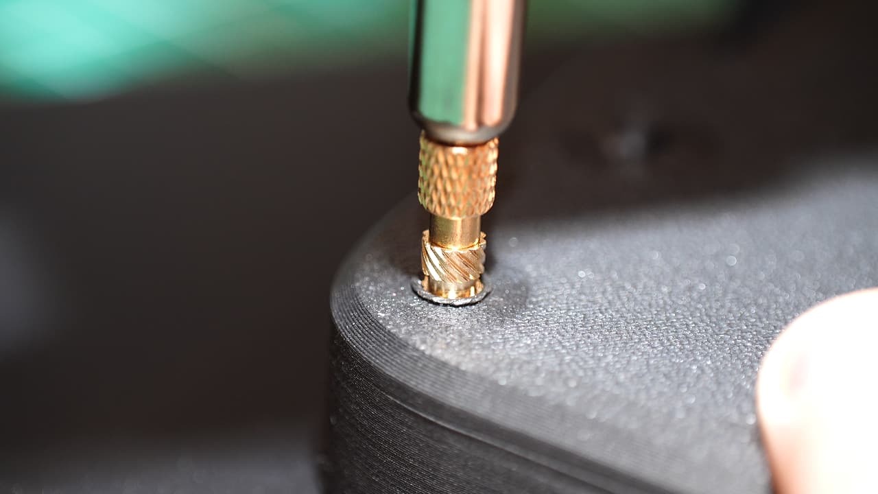 Press in the 4 top inserts and 2 bottom inserts. These 10mm long threaded inserts are super strong. After pushing in the inserts, press down on the surface with a flat piece of metal to cool and ensure flatness.
 -
Insert the top z-block insert
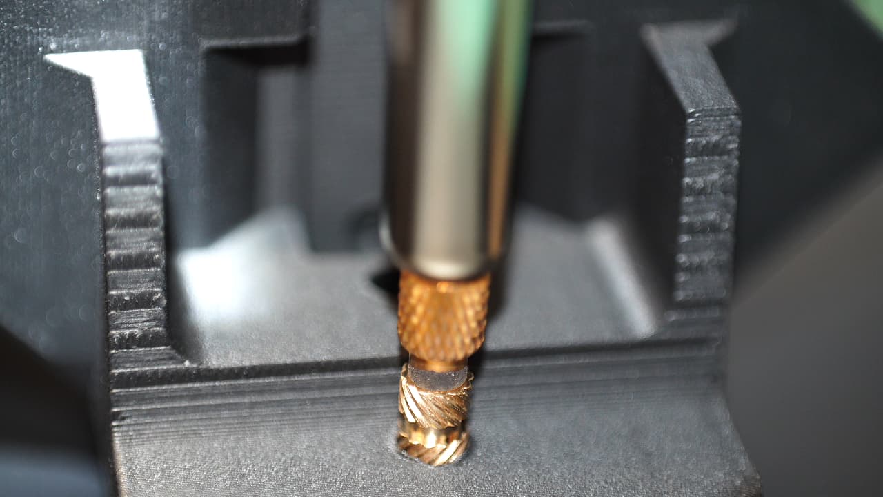 Insert the top z-block insert from the front.
 -
Insert the bottom z-block inserts
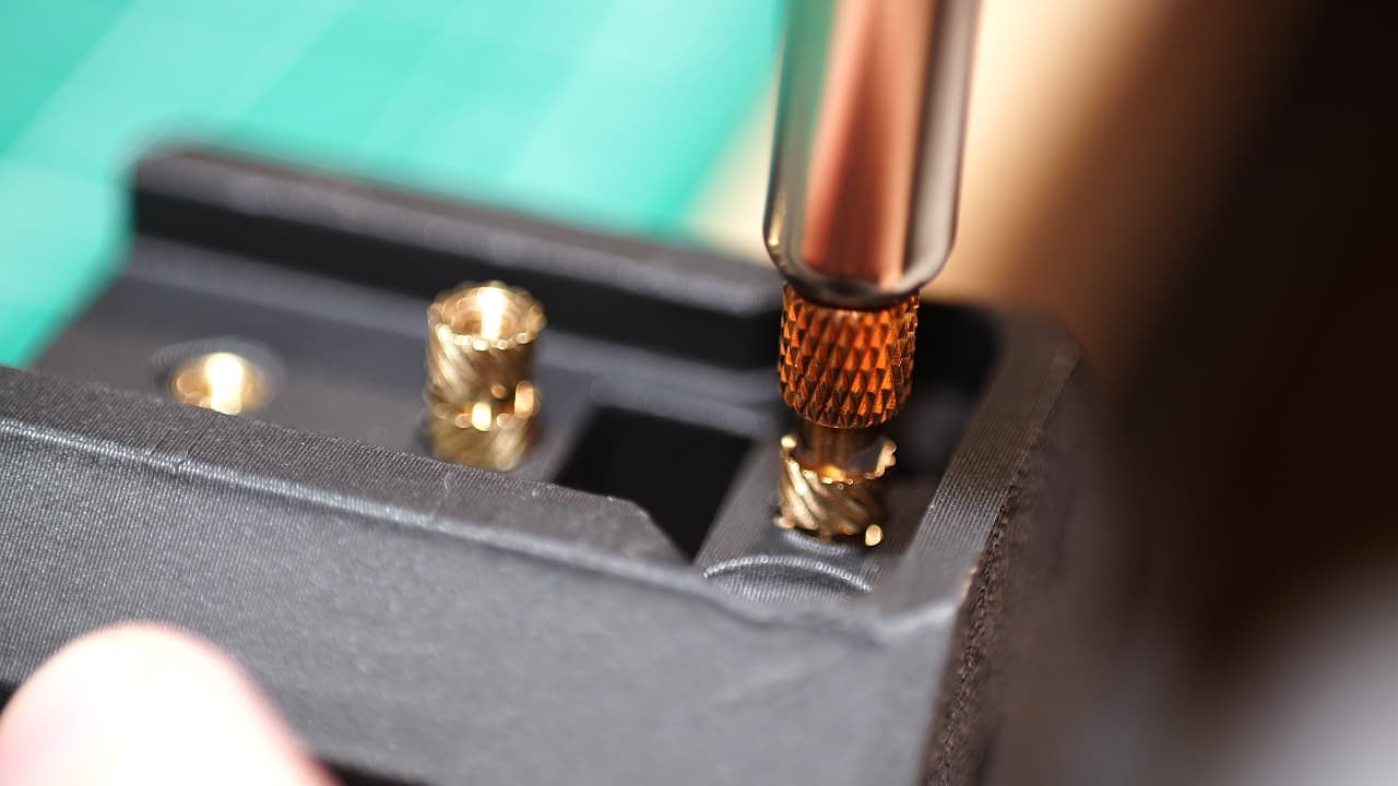 Insert the bottom two z-block inserts from the rear.
 -
Insert the vertical chassis stiffeners
O P T I O N A L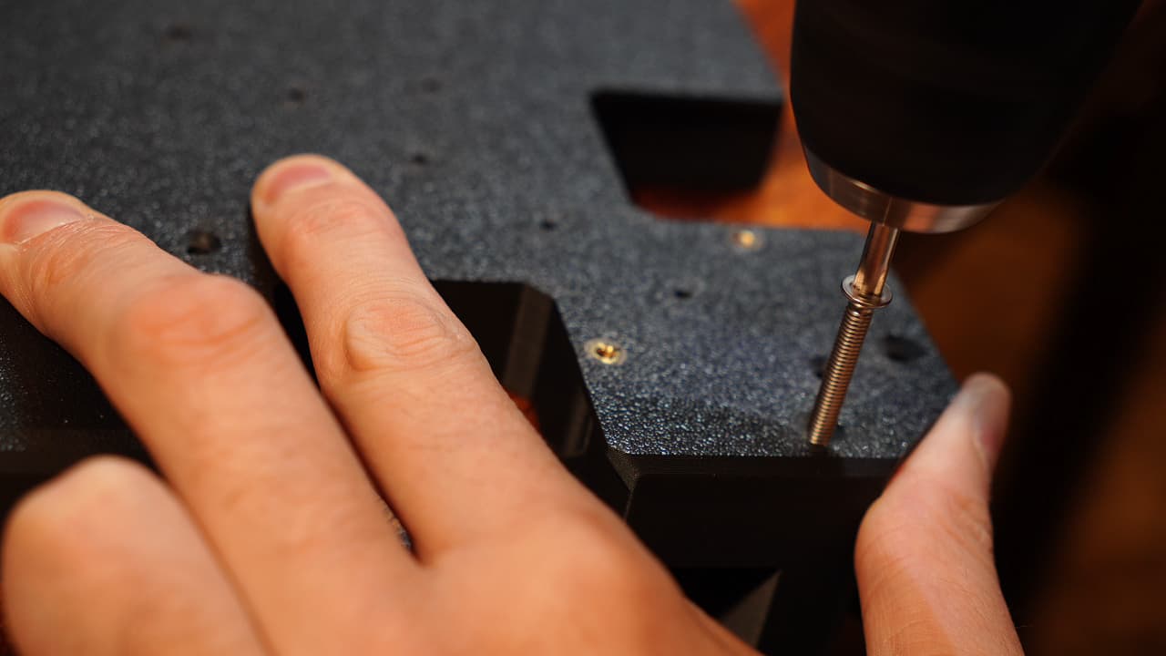 Optionally add the two M4 45mm stiffeners.
 -
Insert the horizontal chassis stiffeners
O P T I O N A L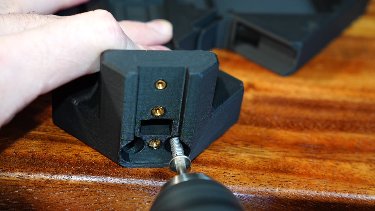 Optionally add the two M5 80mm stiffeners.
 -
Insert the AC input jack
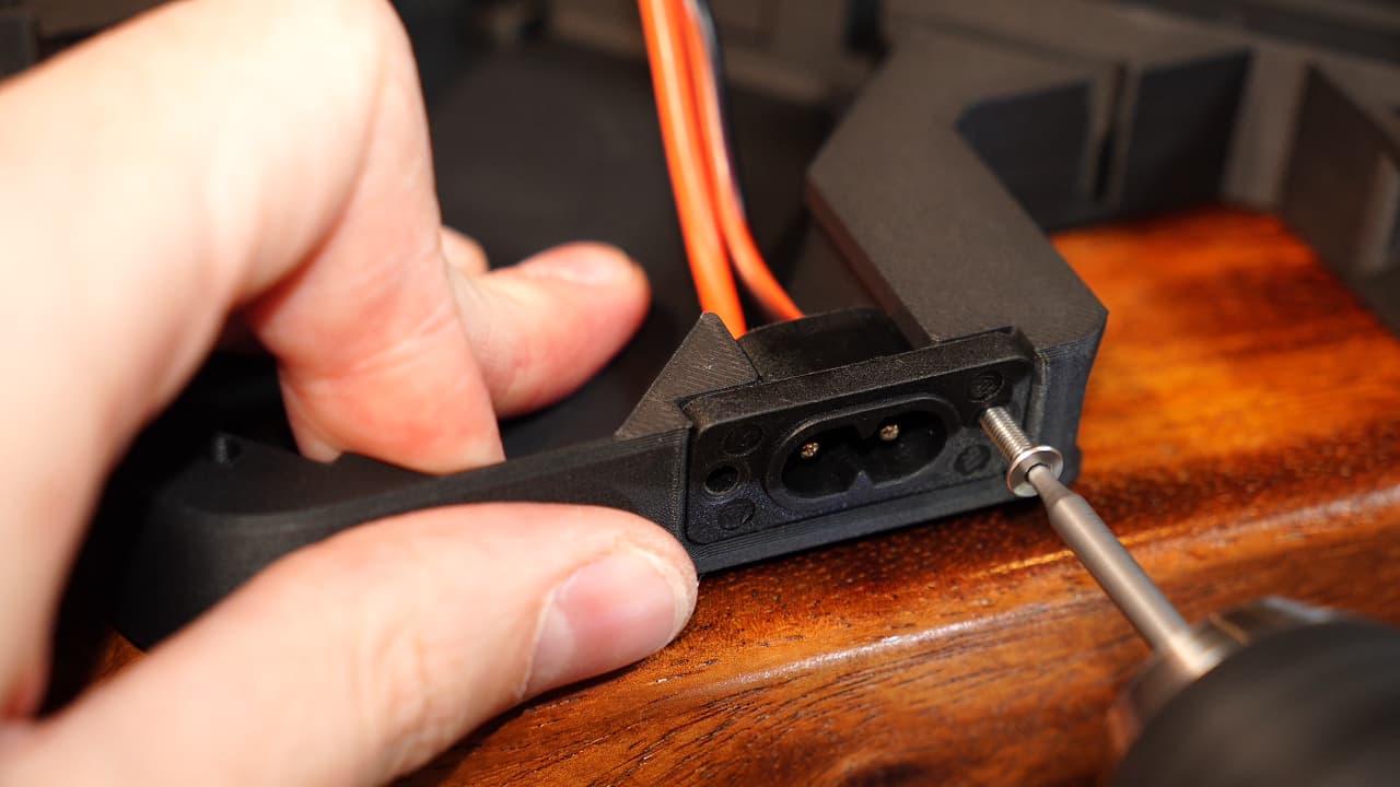 Slide in the AC jack and fasten with two screws.
M314mm
Slide in the AC jack and fasten with two screws.
M314mm -
Modify PSU
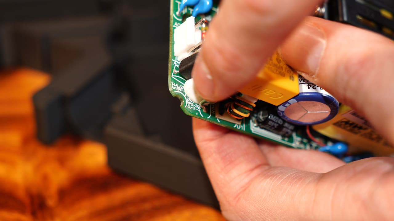 Bevel the two corners of the PSU that face outwards. The cut should bisect the screw post holes.
 -
Link the fans together
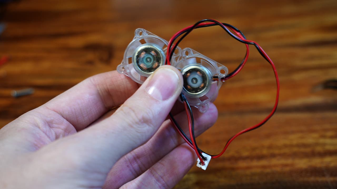 Wire two chassis fans in parallel so that the wire is long enough to reach the ports on the left of the MCU.
 -
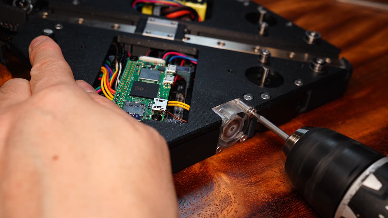
Insert the right fan
 Insert the fan and secure the bottom two screw holes.
M314mm
Insert the fan and secure the bottom two screw holes.
M314mm -
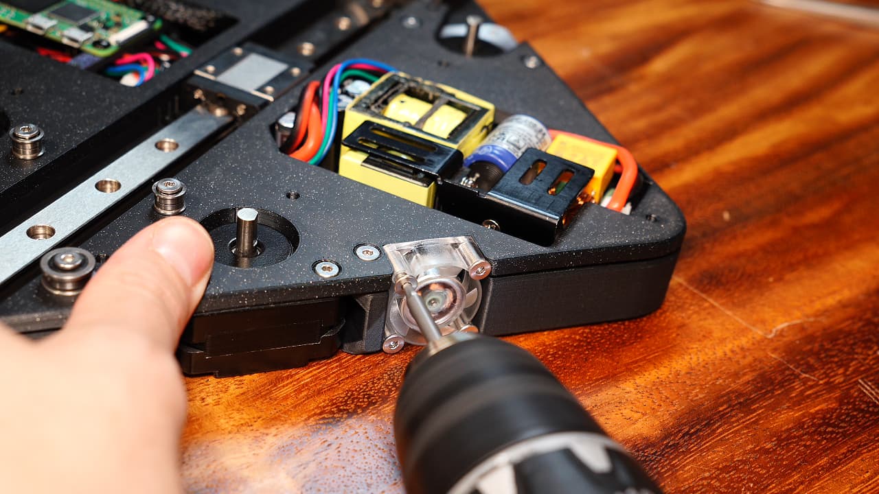
Insert the left fan
 Insert the fan and secure the bottom two screw holes.
M314mm
Insert the fan and secure the bottom two screw holes.
M314mm -
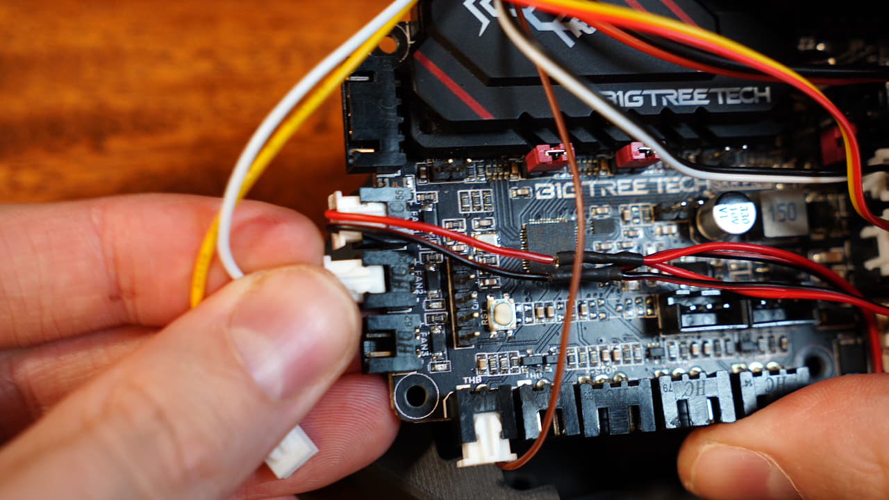
Plug in the fans
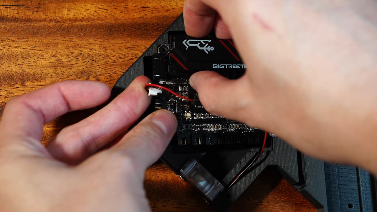 Plug in the chassis fans to the top port of the MCU.
 -
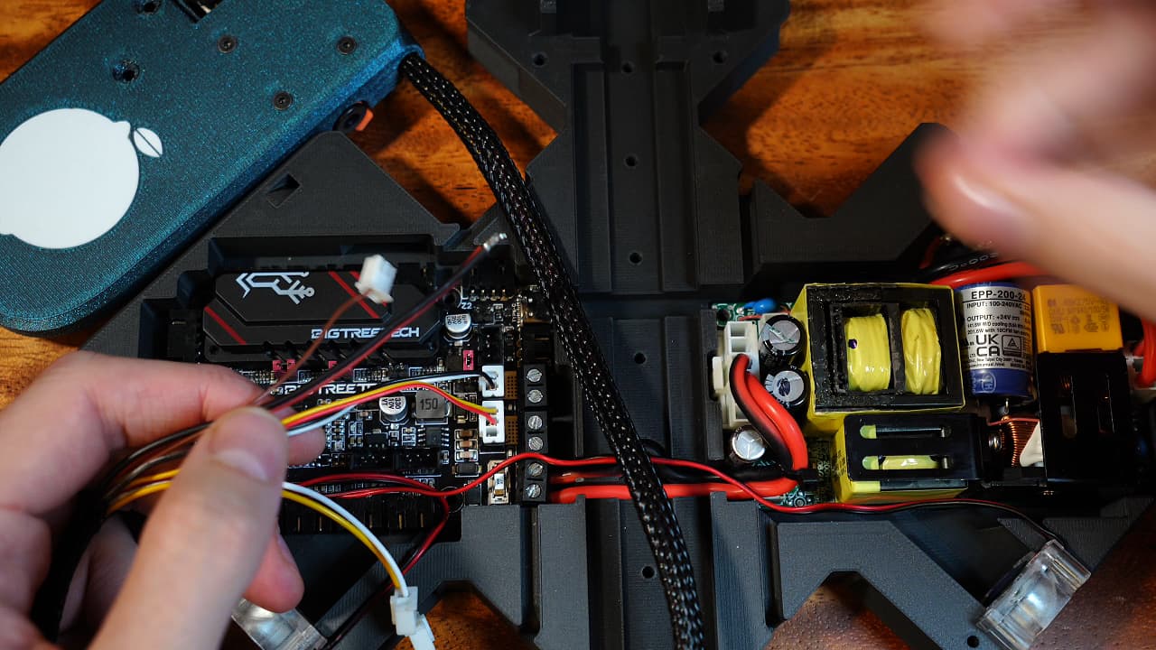
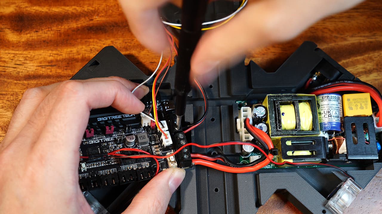
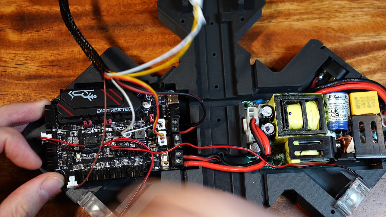
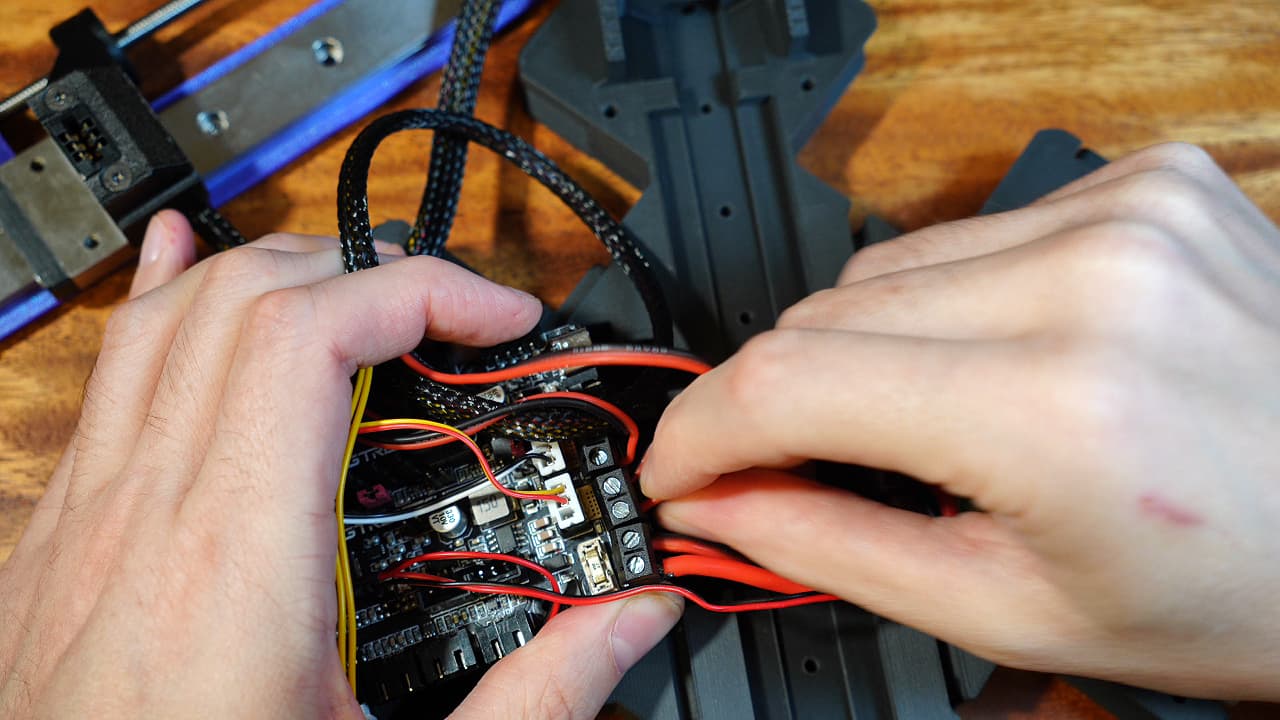
Plug in the power wires
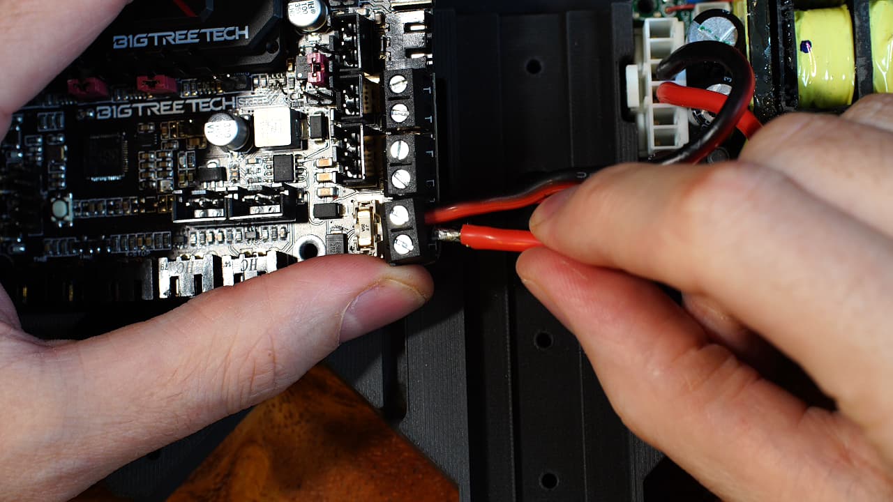 Connect the power wires to the PSU and cut to length, tin the ends, and plug in. The gauge of these wires should be 18AWG or thicker. 14AWG is the largest wire the terminal blocks can accept.
 -
Plug in the probe connectors
 Connect the two probe connectors as shown- B/W on top, Y/R on bottom.
 -
Plug in the hotend heater wires
 Insert the two heater wires into the top terminal block.
 -
Plug in the hotend thermistor connector
 Insert the thermistor wire into the bottom left port.
 -
Plug in the hotend fan connector
 Insert the hotend fan connector into the second port.
 -
Plug in the part cooling fan connector
 Insert the part cooling fan connector into the third port.
 -
Plug in the bed thermistor
 Bring over the z-axis and insert the heat bed thermistor connector next to the hotend thermistor.
 -
Plug in the bed heater
 Insert the heat bed power wires into the middle terminal block and tighten.
 -
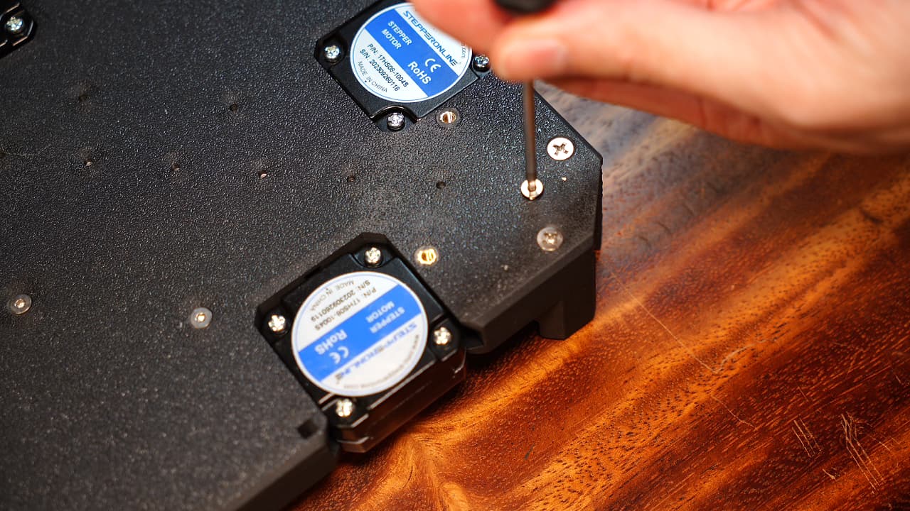
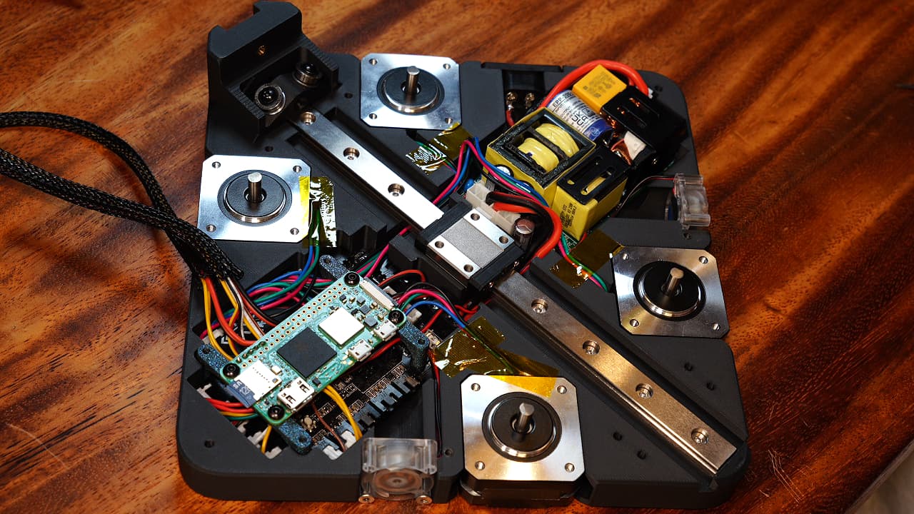
Insert the motors
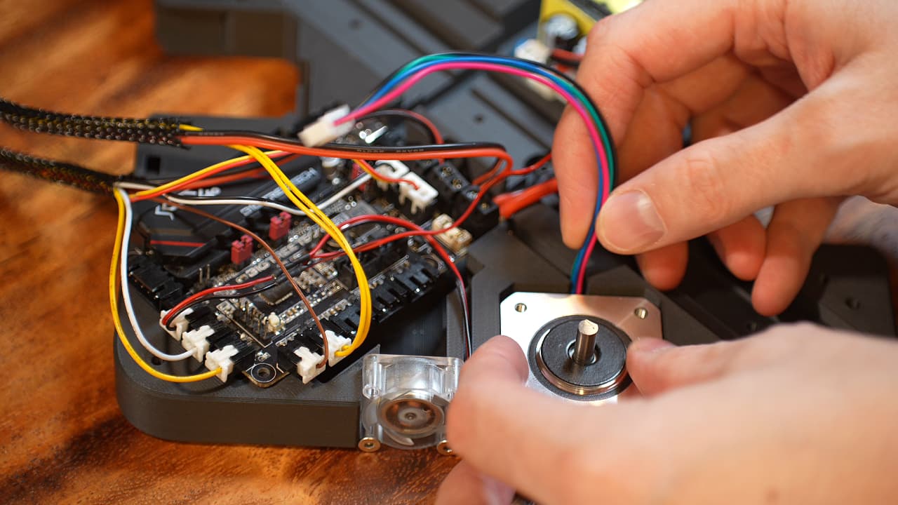 Bottom left motor has 15cm wire, bottom right has 23cm wire, top right has 15cm wire, top left has 10cm wire.
 -
Plug in the motors
 Referring to the SKR Pico pinout, port E connects to the top left (extruder) motor, port X to the bottom left (A) motor, port Y to the bottom right motor (B), port Z1 to the top right (Z-Axis) motor.
 -
Solder the serial connector
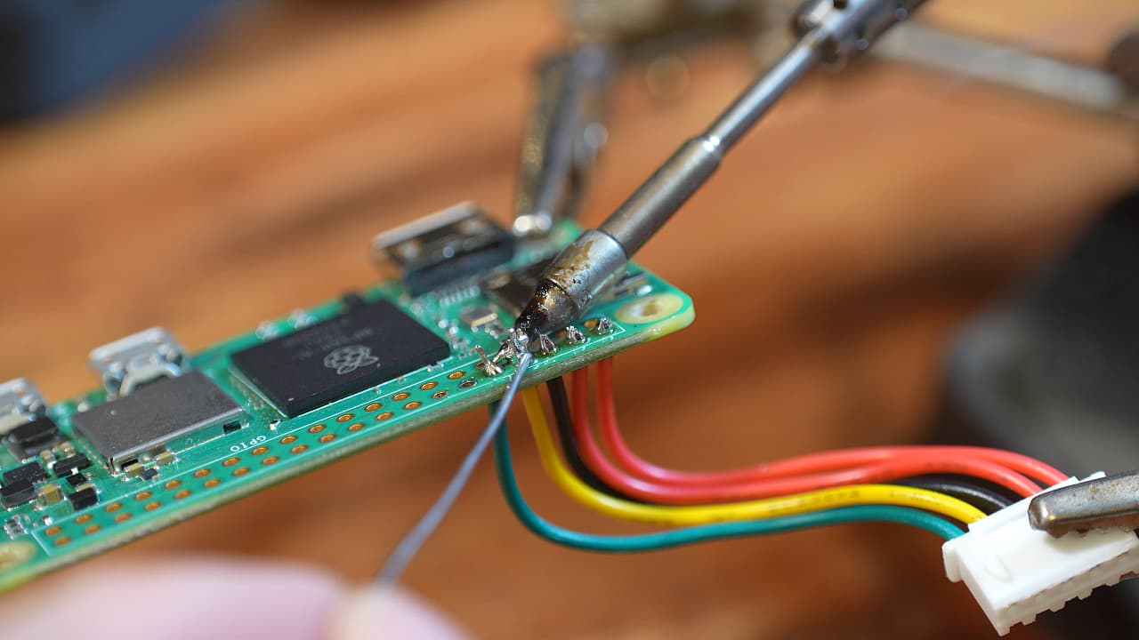 Solder the Raspberry Pi connector as shown. You can also try using right angle pins!
 -
Plug in the Raspberry Pi
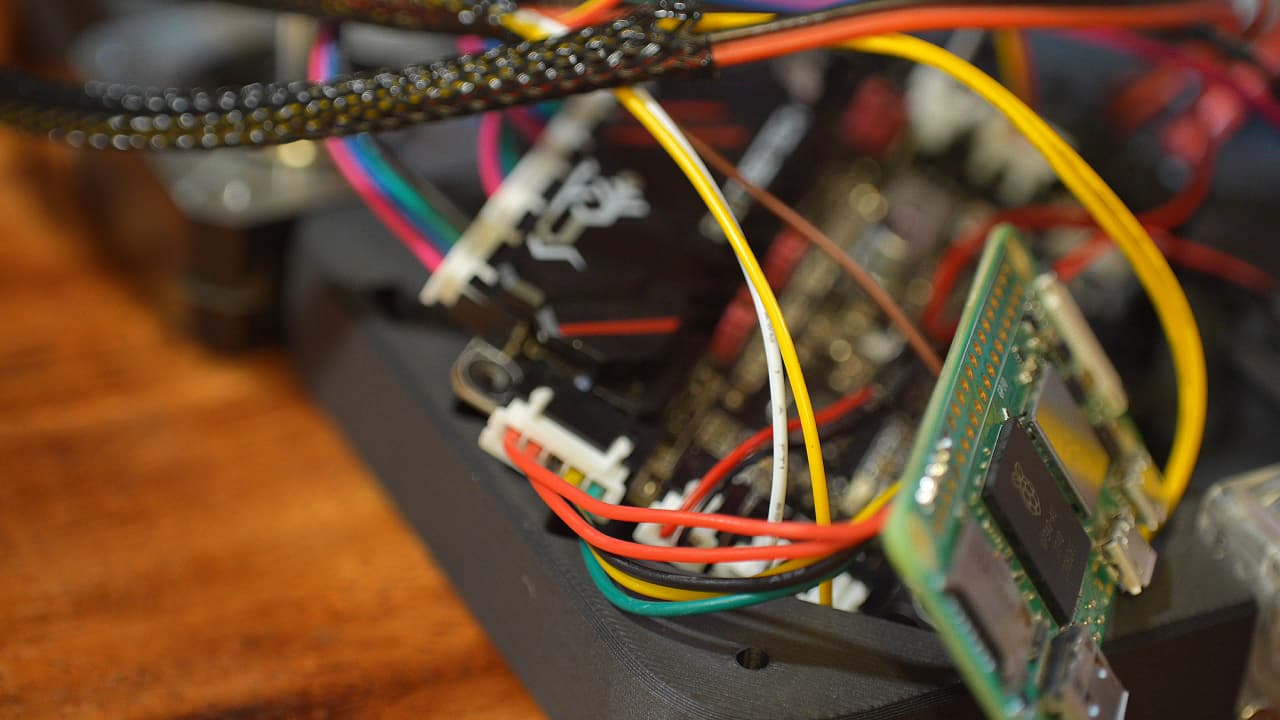 Connect the Raspberry Pi to the serial port.
 -
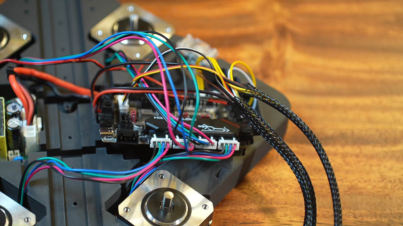
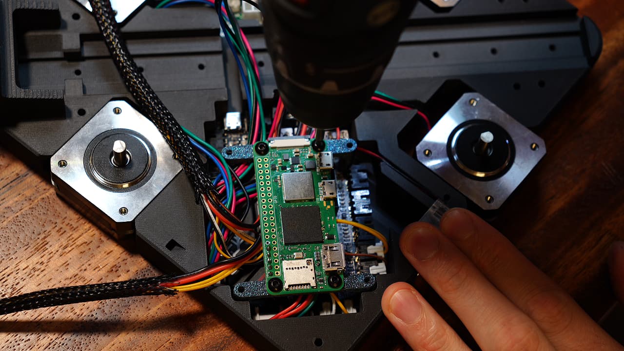
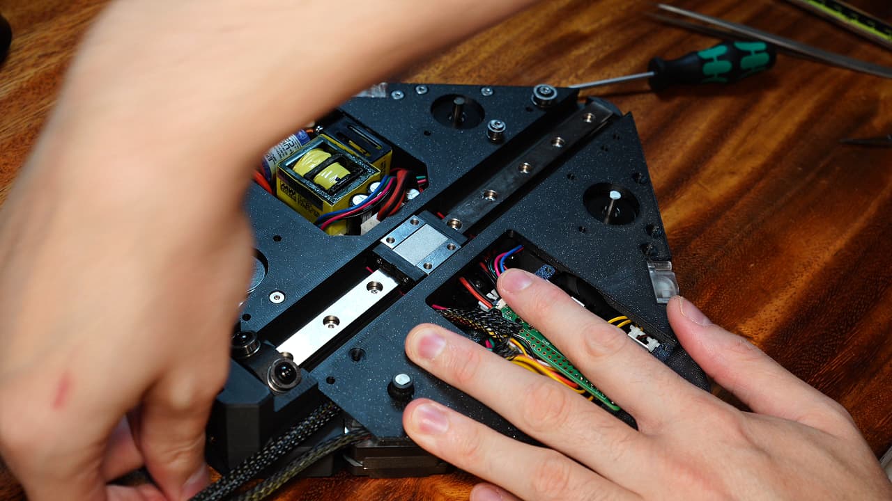
Smush the MCU
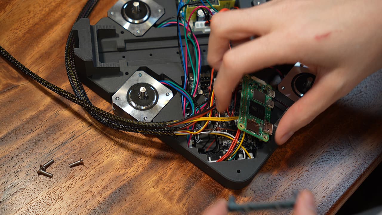 Smoosh the wires up and press the MCU into place.
 -
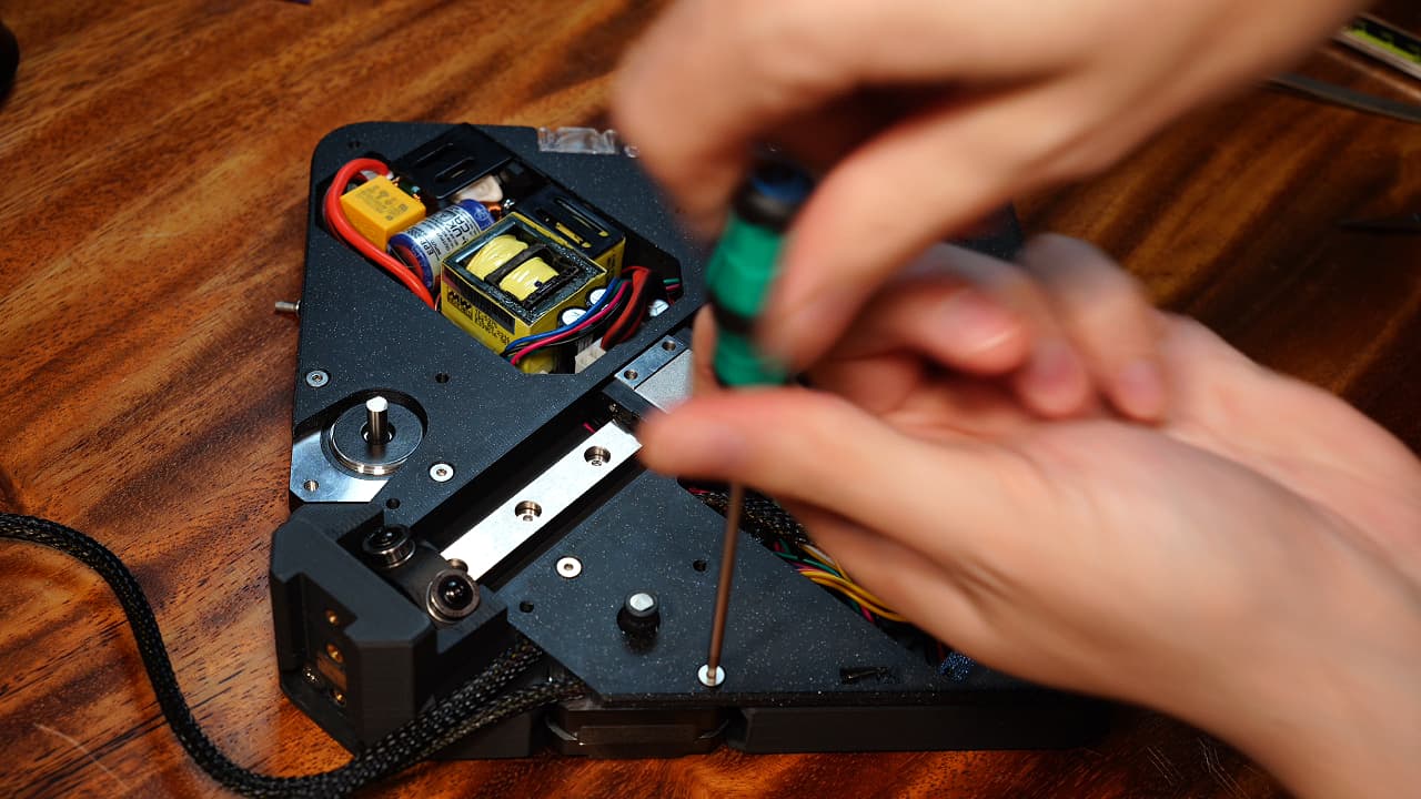
Insert the risers
 Install the risers, the left one covers all the wires, and the right one covers all except the extruder motor's wires.
 -
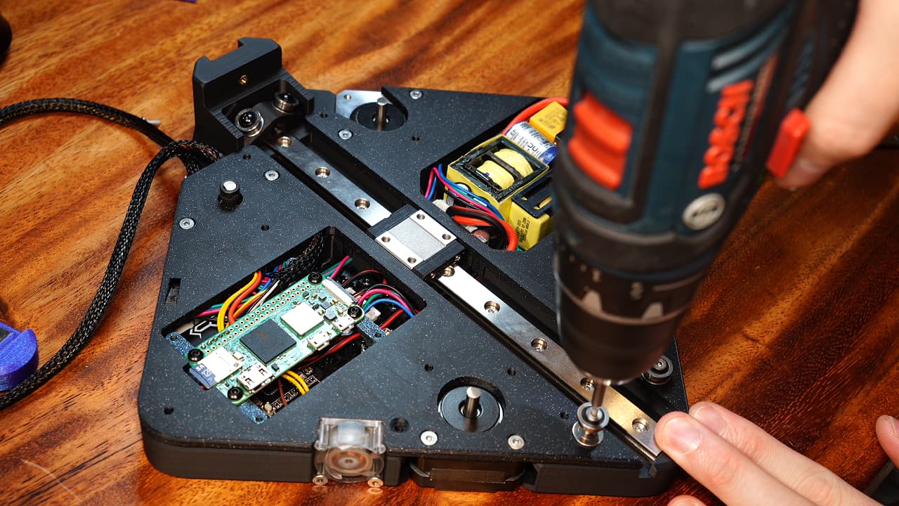
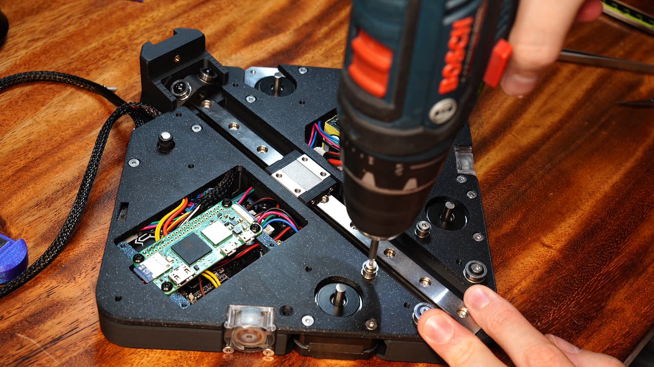
Screw in the risers
 Flip it over and fix the riser in place with two 8mm countersinks.
M38mm
Flip it over and fix the riser in place with two 8mm countersinks.
M38mm -
Attach Raspberry Pi
 Use four screws to attach the Raspberry Pi.
M2.56mm
Use four screws to attach the Raspberry Pi.
M2.56mm -
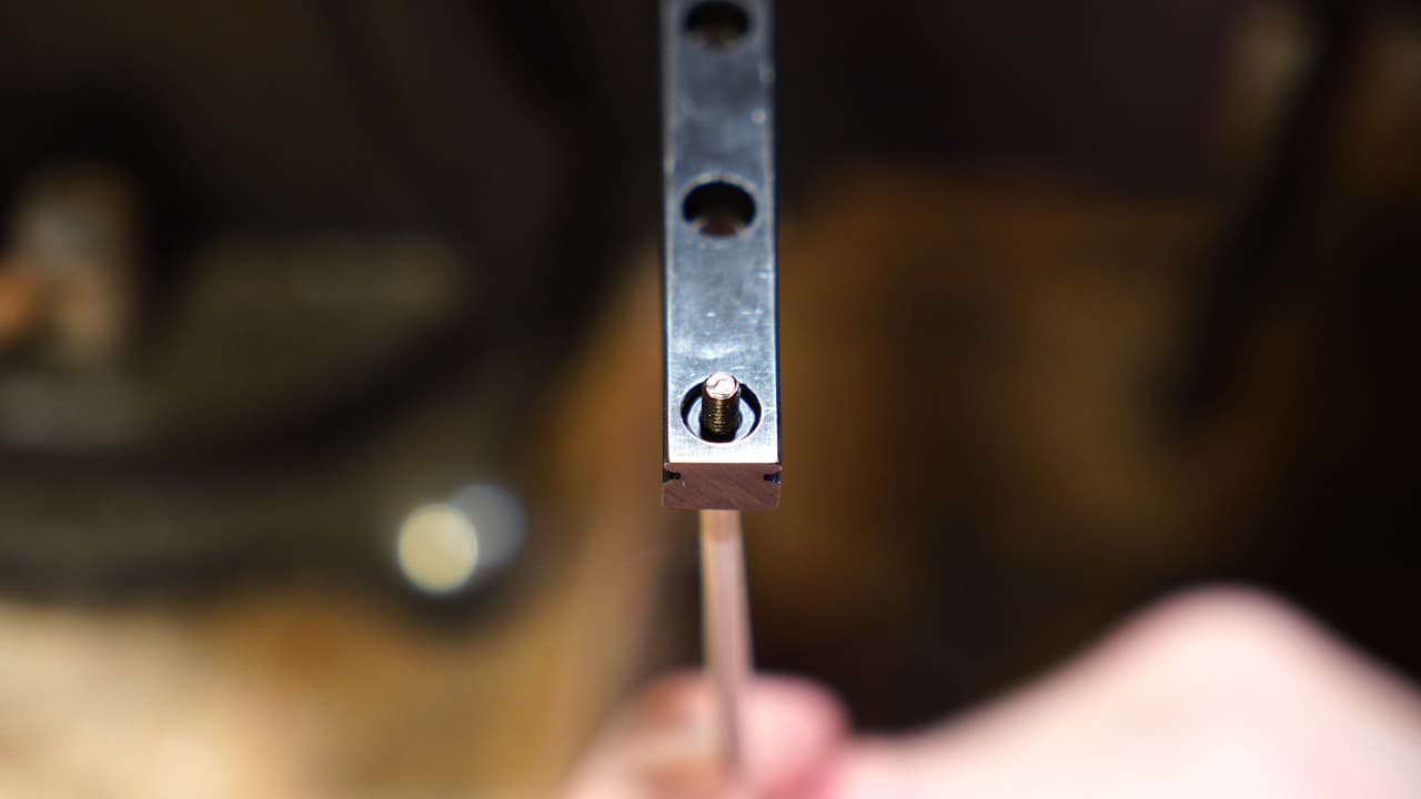
Insert nut
 Insert a nut onto the Y-Rail (MGN12C) by pulling it in from behind with a screw.
 -
Install tensioner
 On the same rail, install the tensioner over the nut.
 -
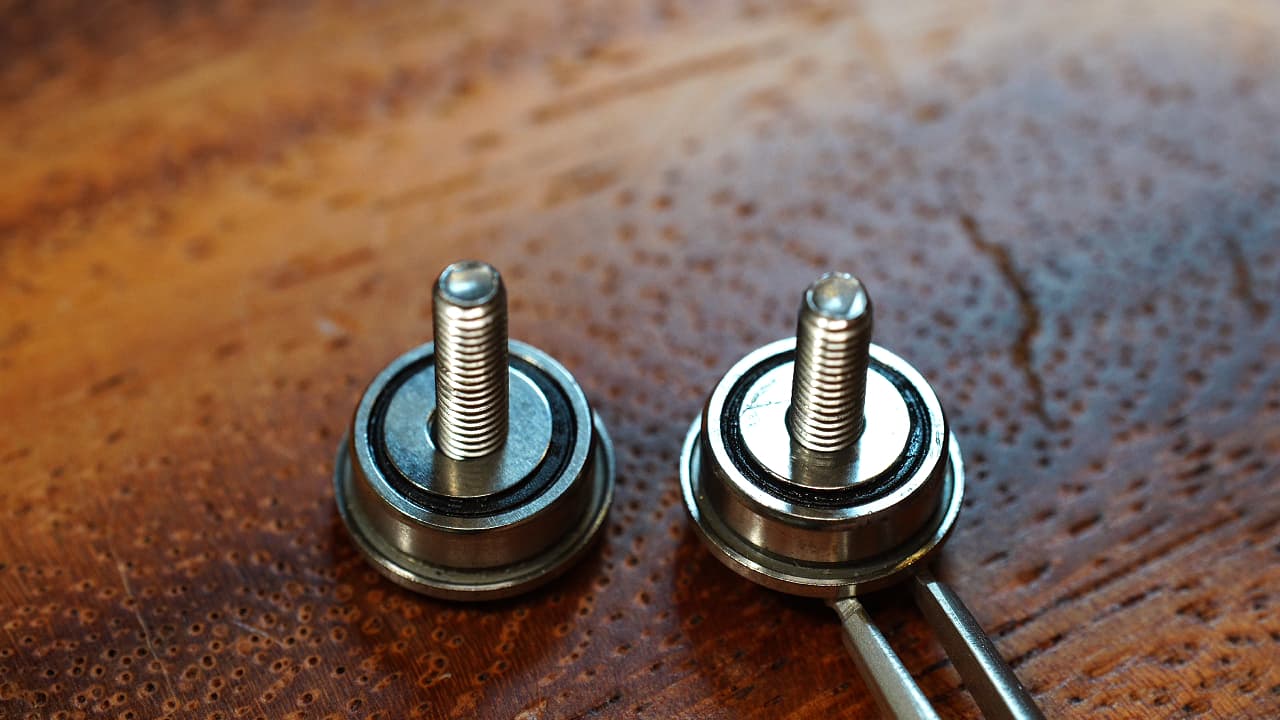
Prepare two posts
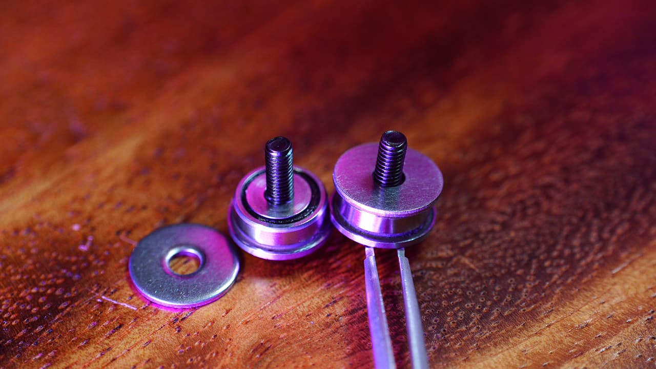 Onto the screw, drop a big bearing, a shim, and a washer.
M312mm
Onto the screw, drop a big bearing, a shim, and a washer.
M312mm -
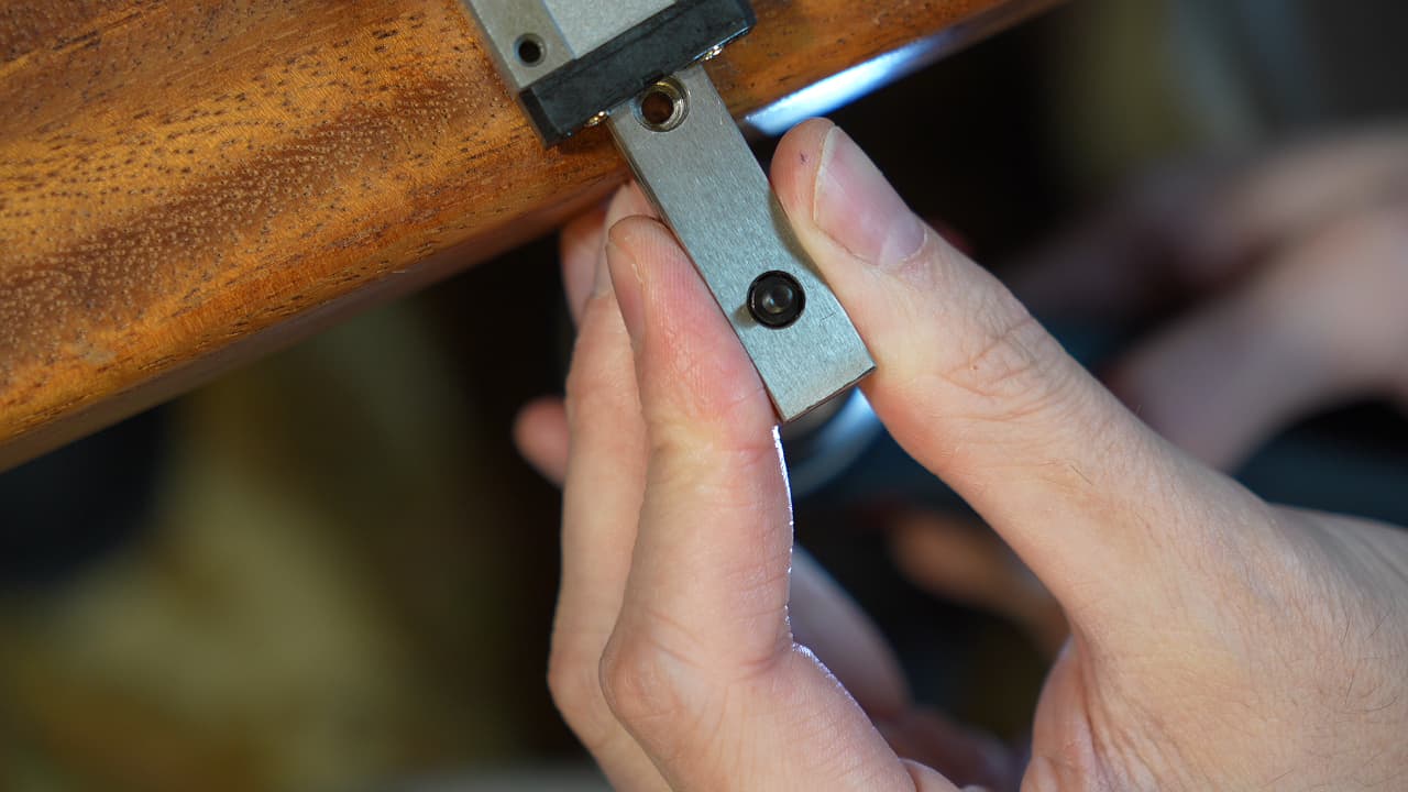
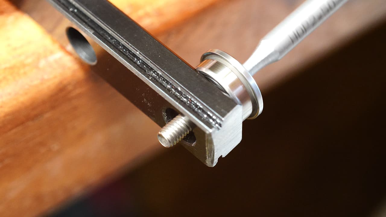
Install the posts
 Install the bearing posts into the tensioner.
 -
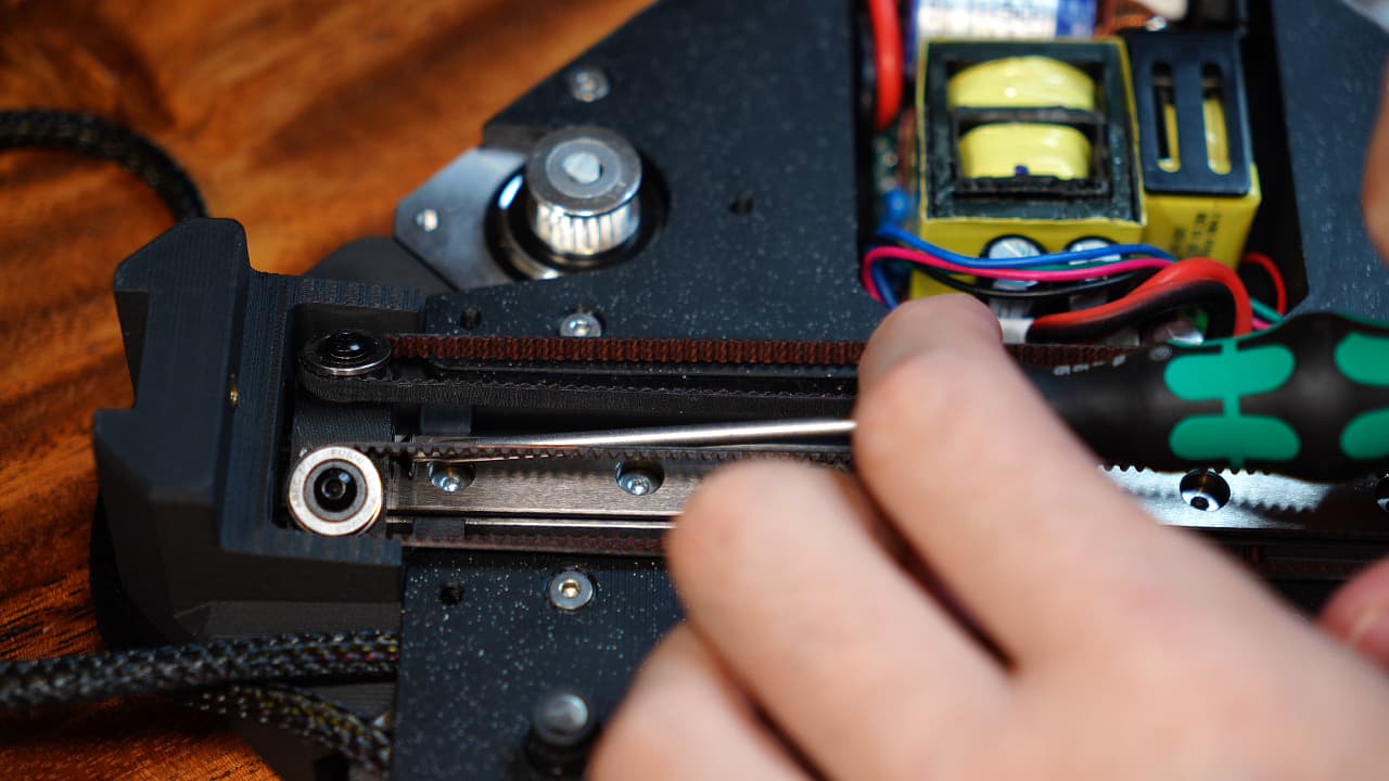
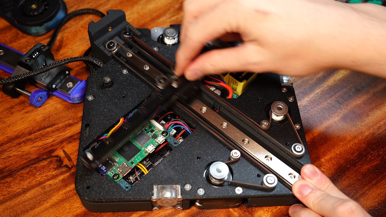
Install the rail
 Slide in the rail. You might want to tap it down with a mallet. Verify the wires that run under the rail are tidy.
 -
Fasten the rail
 Screw the rail to the chassis. You must go slow, alternate short rotations and don't overheat the plastic.
M314mm
Screw the rail to the chassis. You must go slow, alternate short rotations and don't overheat the plastic.
M314mm -
Insert the bonus screw
 From the bottom, fasten the rail tightly to the chassis.
M320mm
From the bottom, fasten the rail tightly to the chassis.
M320mm -
Tape the motors
 Tape the motors. Without tape, the wires will fly away. You need to tape it before installing the mid plates.
 -
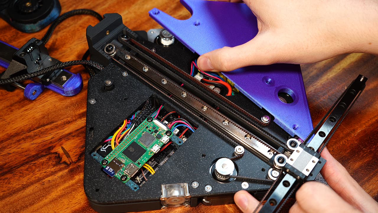
Install the right midplate
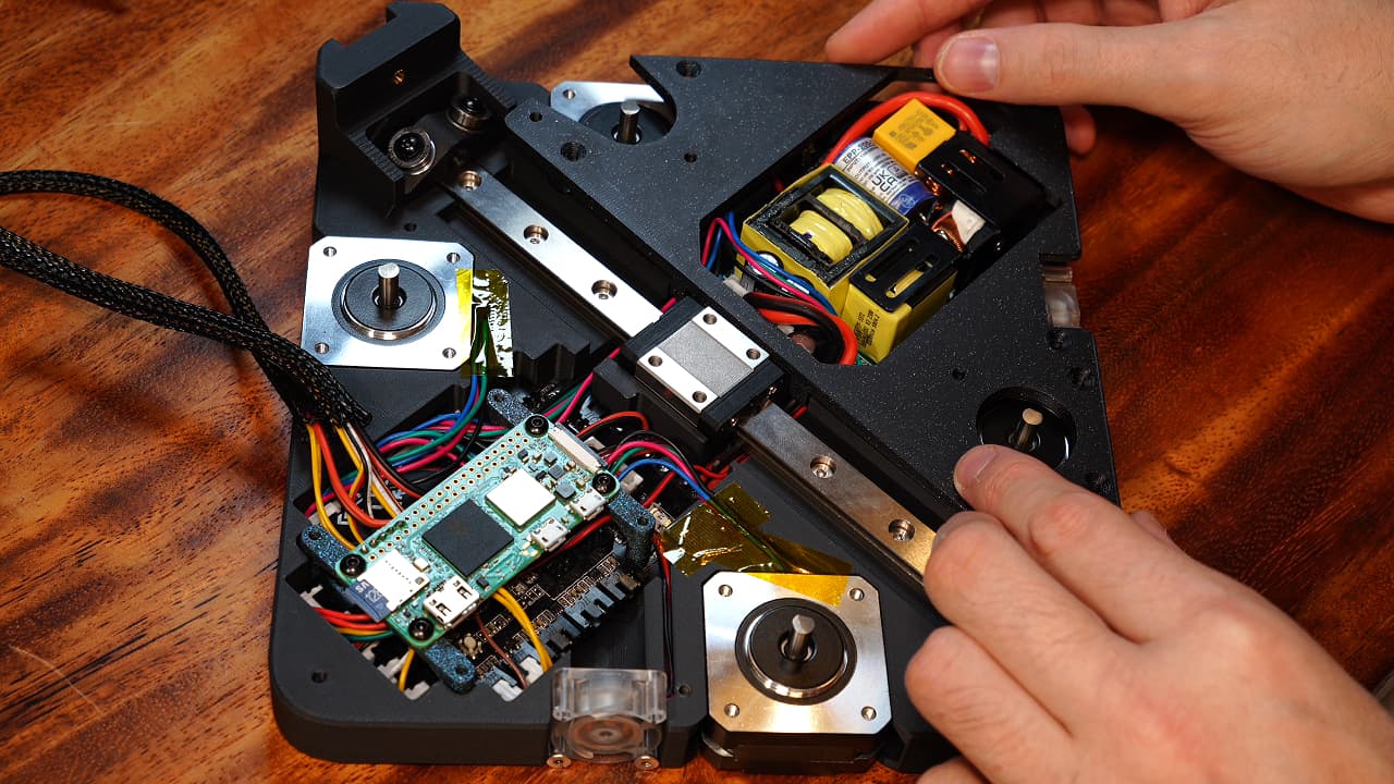 Drop the right midplate on top of the motors, making sure you can press it flat. Verify from every angle that there is no gap.
 -
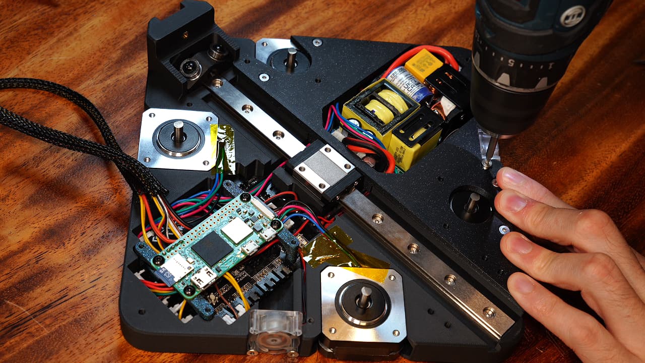
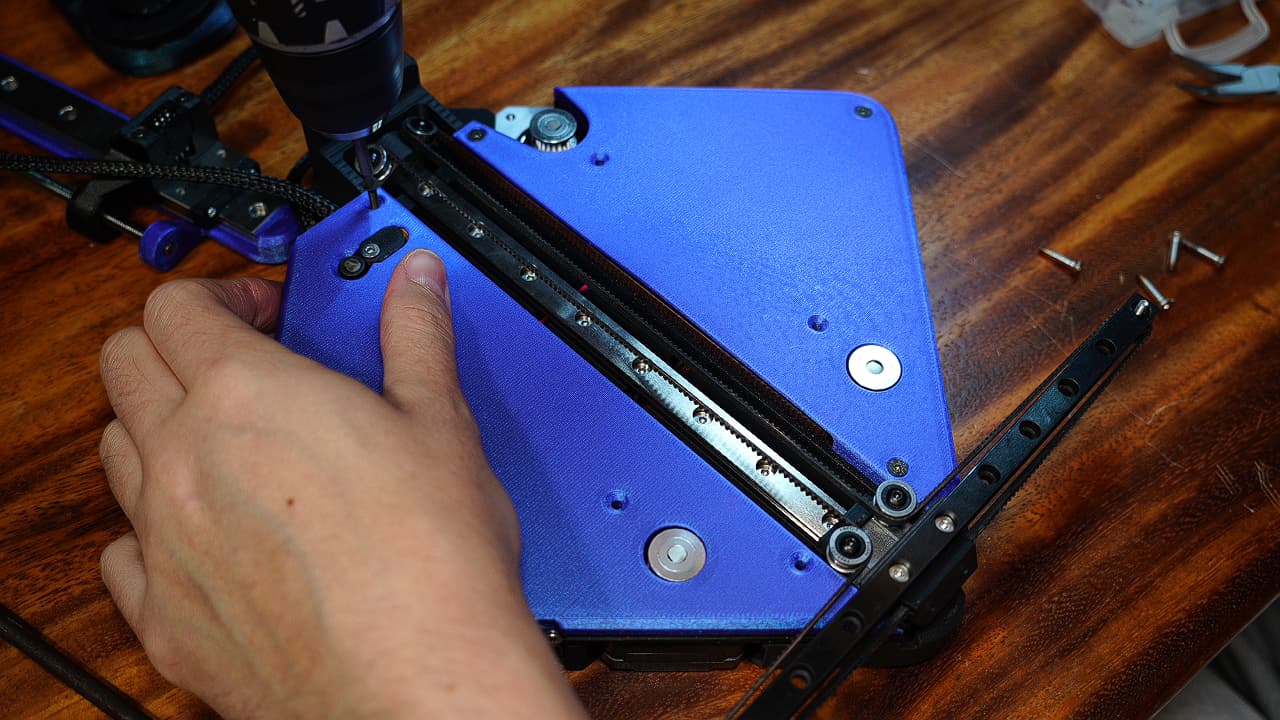
Secure the right motors
 Secure the motors to the right midplate, filling the four countersunk motor mount holes.
M38mm
Secure the motors to the right midplate, filling the four countersunk motor mount holes.
M38mm -
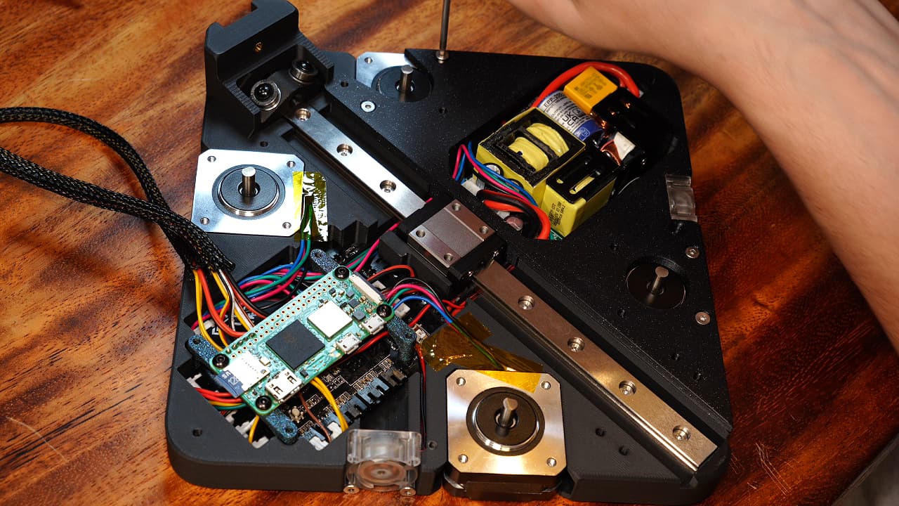
Install the extra screw
 Add another screw to further secure the midplate to the chassis.
M320mm
Add another screw to further secure the midplate to the chassis.
M320mm -
Install the lower pulley
 Onto the screws, drop a big bearing, a medium shim, and a big washer. Screw it all the way through the chassis.
M325mm
Onto the screws, drop a big bearing, a medium shim, and a big washer. Screw it all the way through the chassis.
M325mm -
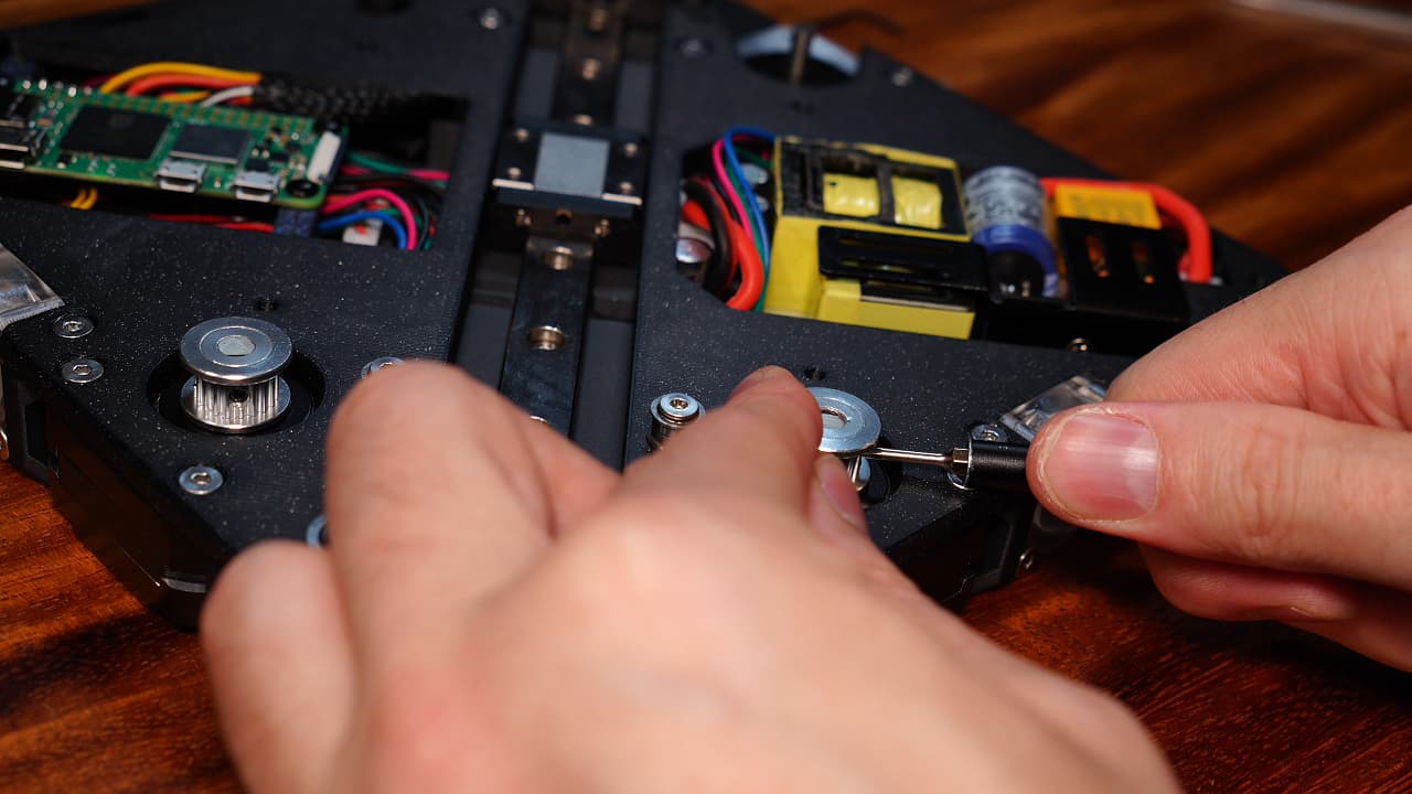
Install the upper pulley
 Onto the screws, drop a small flanged bearing, a small shim, another small flanged bearing, and another small shim. This post threads into the motor. The flanges serve as guides for the belt.
M314mm
Onto the screws, drop a small flanged bearing, a small shim, another small flanged bearing, and another small shim. This post threads into the motor. The flanges serve as guides for the belt.
M314mm -
Install extruder gear
 On the top left motor, and using several fingers, line up the top of the extruder gear with a pulley and fasten the grub screw to the flat side of the shaft.
 -
Install left midplate
 Insert the wire harnesses into the slots in the midplate and lay the midplate into position. Verify there is no gap.
 -
Tug the cables
 Remove the slack in the cables.
 -
Insert the motor mount screws
 Secure the motors to the left midplate, filling the four countersunk motor mount holes with 8mm countersinks.
M38mm
Secure the motors to the left midplate, filling the four countersunk motor mount holes with 8mm countersinks.
M38mm -
Insert the lower pulley
 Same as the right one.
 -
Insert the upper pulley
 Same as the right one.
 -
Install the extra screw
 Add another screw to further secure the midplate to the chassis.
M320mm
Add another screw to further secure the midplate to the chassis.
M320mm -
Finish right fan
 Secure the right fan's top two screw holes.
M314mm
Secure the right fan's top two screw holes.
M314mm -
Finish left fan
 Secure the left fan's top two screw holes.
M314mm
Secure the left fan's top two screw holes.
M314mm -
Install left drive pulley
 Temporarily put two sheets of paper under the pulley before tightening the grub screw to the flat side of the shaft. If there are two grub screws, tighten them both but one should be on the flat side of the shaft.
 -
Install right drive pulley
 Repeat on the right. Verify the pulleys are friction-free by grabbing the pulley forcefully and rotating it a full circle. If it catches on something, it's going to show up in your prints.
 -
Modify X rail
 Cut one hole off the X rail (MGN9C).
 -
Install right drive pulley
Add a nut to both sides of the rail. -
Create bearing posts
 On the screws, drop a big bearing and a medium shim.
M314mm
On the screws, drop a big bearing and a medium shim.
M314mm -
Install bearing posts
 On both sides of the rail tighten down both bearing posts.
 -
Drop on the spacer
 Drop the spacer (printed) onto the Y axis carriage.
 -
Attach the X rail
 Drop the X rail on top of the spacer and screw it in with two screws.
M320mm
Drop the X rail on top of the spacer and screw it in with two screws.
M320mm -
Create bearing towers
 On the screws, drop a big bearing, a medium shim, a large washer, a small shim, a small flanged bearing, small shim, small normal bearing, and small shim.
M316mmThe belt rides on the normal bearing and the flanged bearing prevents it from riding up.
On the screws, drop a big bearing, a medium shim, a large washer, a small shim, a small flanged bearing, small shim, small normal bearing, and small shim.
M316mmThe belt rides on the normal bearing and the flanged bearing prevents it from riding up. -
Install bearing towers
 Screw the two bearing towers into the top positions in the Y carriage.
 -
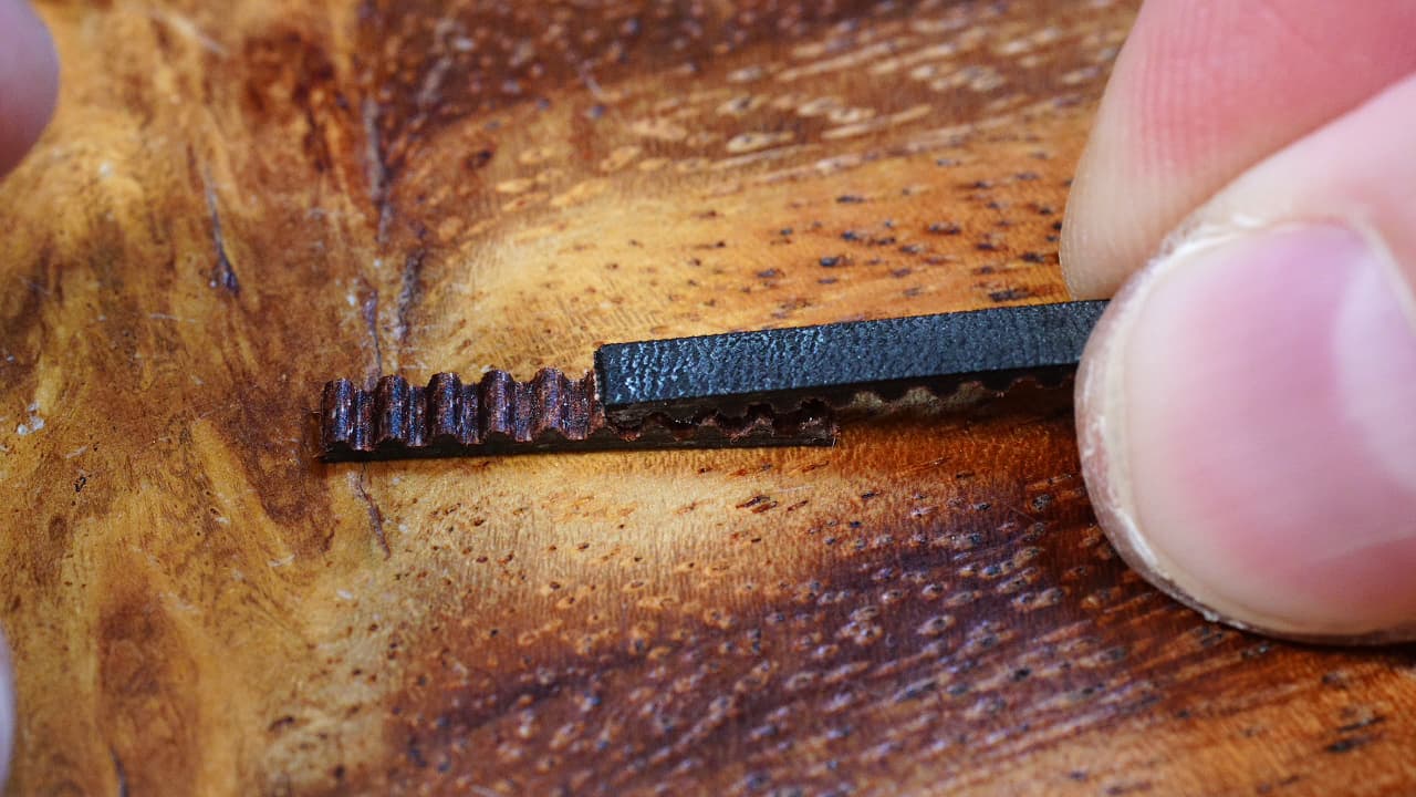
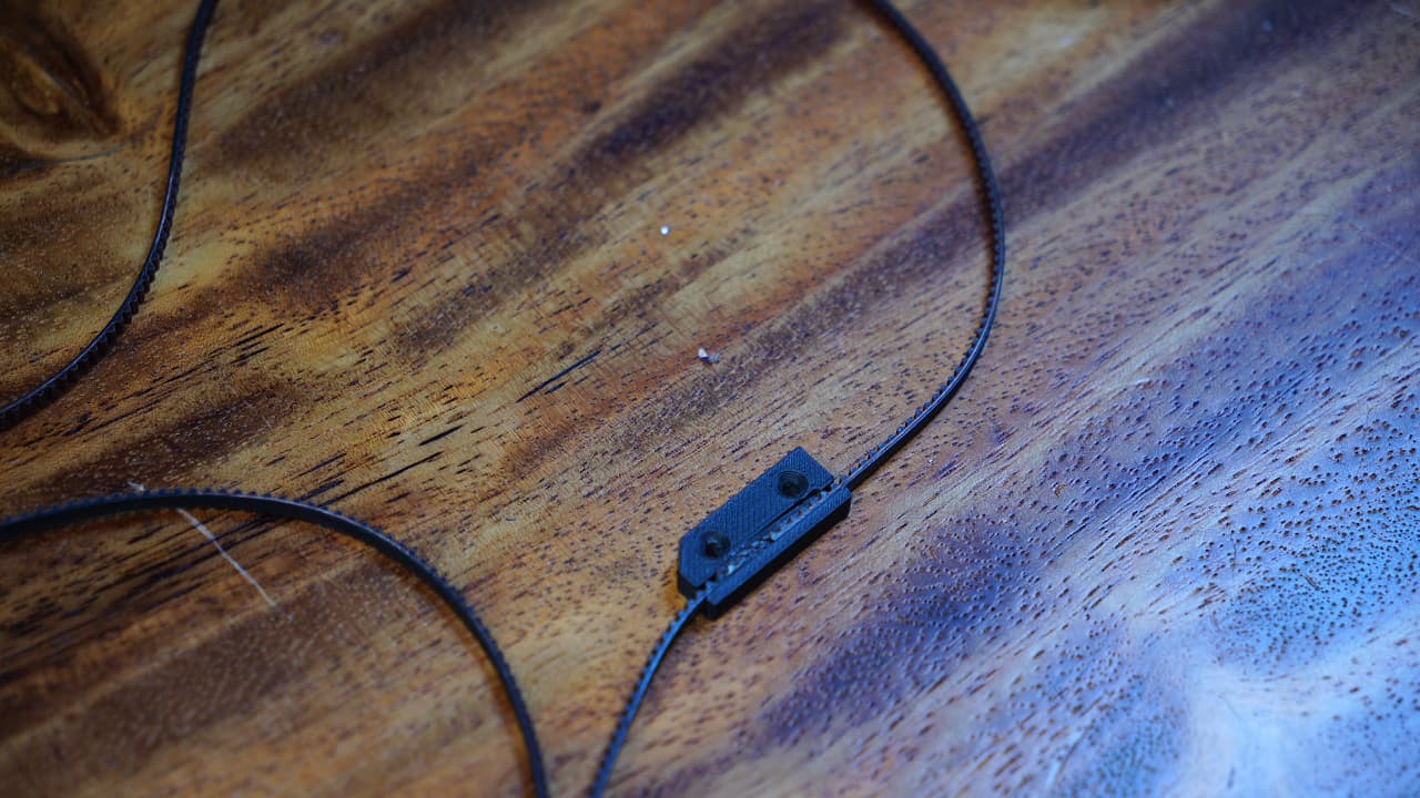
Cut a piece of belt
 Cut a piece of belt that precisely fits into the recess in the belt clip.
 -
Dap some super glue
O P T I O N A L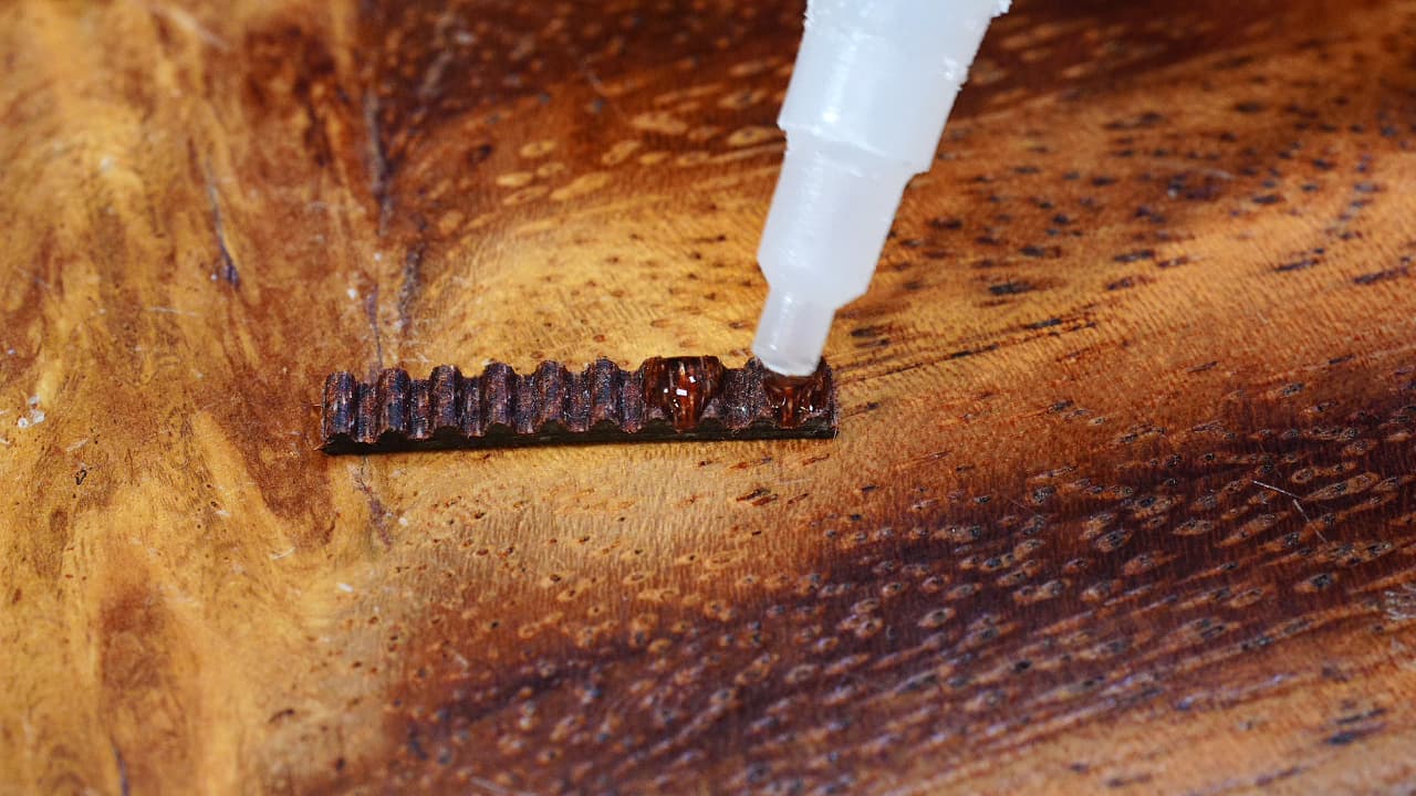 Dap some super glue on the belt. The glue is not required, but it really makes it easier to put the belt into the clip.
 -
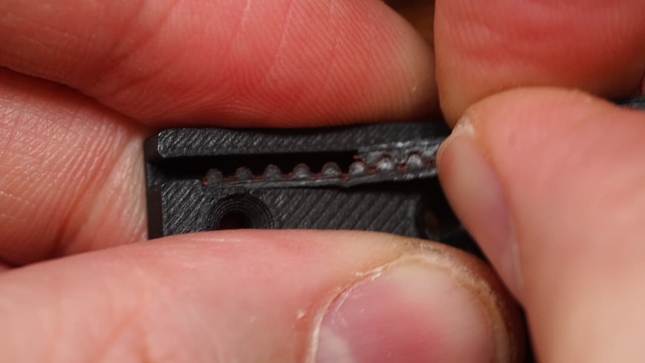
Link the belts
 Hold the long piece of belt to the short one, overlapping half of it as shown.
 -
Insert one side
 Insert the belt into the clip and verify that the short belt is seated properly.
 -
Insert the other side
 Insert the other side of the belt temporarily. You can trim it later.
 -
Lubricate belts
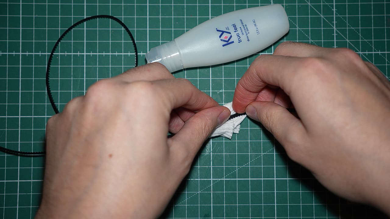 Lubricate the sides of the belt (not the teeth) with silicone based lube. Don't AT me for using sex lube, it's a joke.
 -
Route the belts
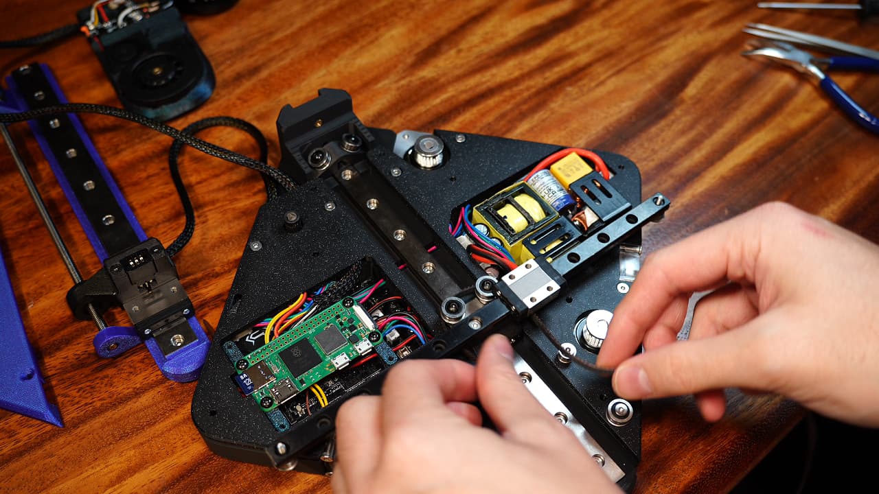 Hook the belt over the towers, placing it on the lowest bearing.
 -
Around the lower bearings
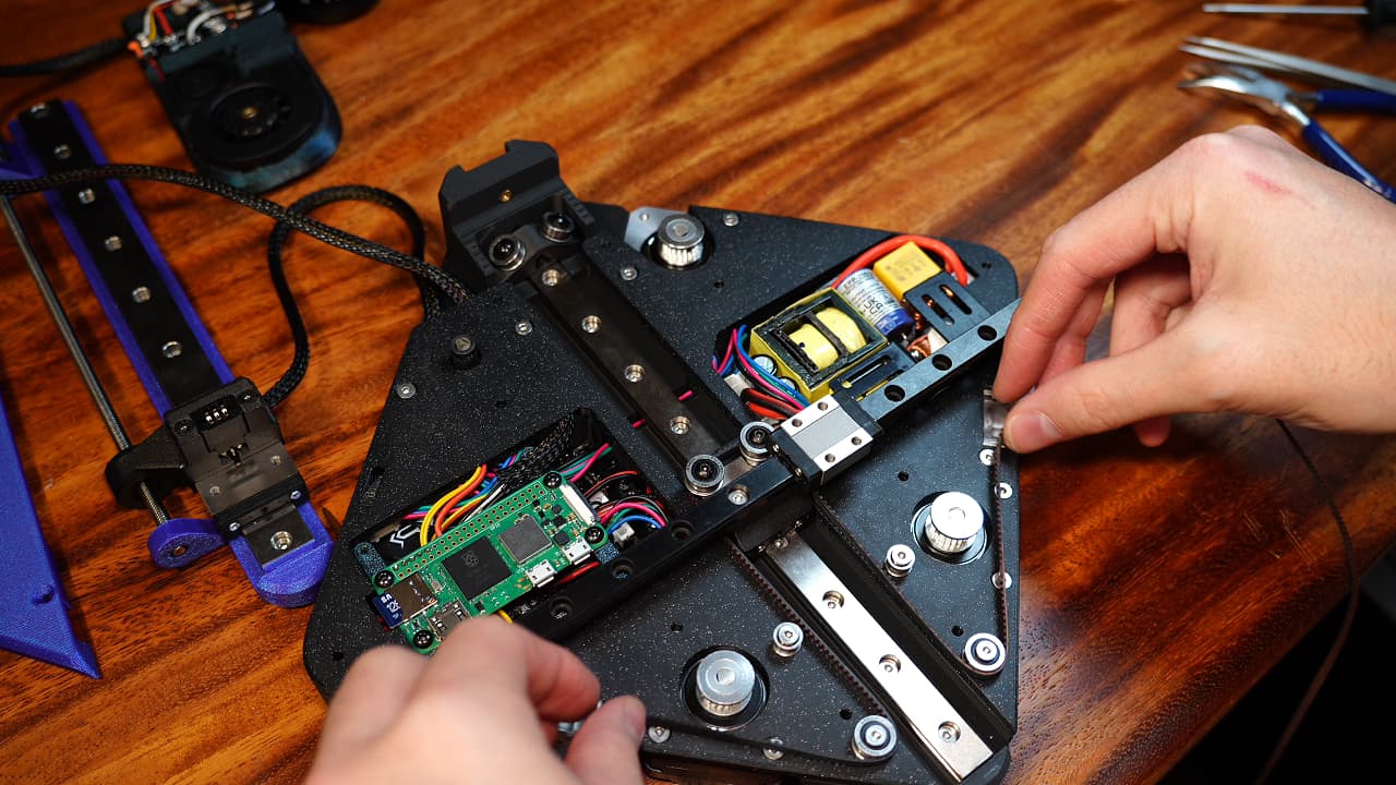 Hook the lower bearings.
 -
Around the upper bearings
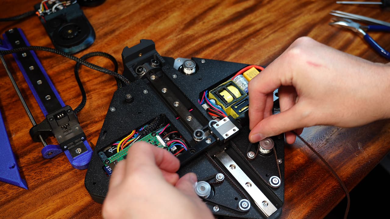 Wrapping around the drive pulleys, hook the upper bearings.
 -
Around the tensioner
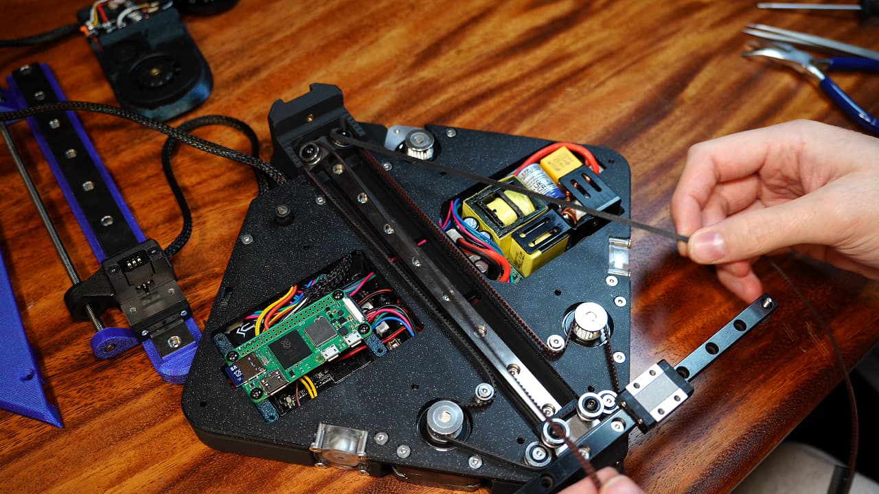 Wrap the belts around the tensioner bearings, the two strands coming down the middle.
 -
Around the tower again
 Hook the tower bearings, this time the upper ones, heading out to the X rail bearings.
 -
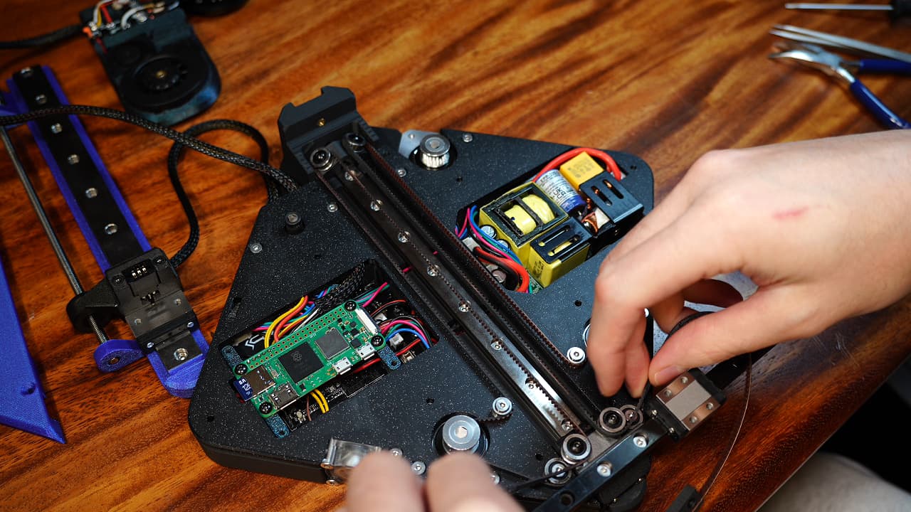
Around the X rail
 Route the belt around the X rail. Trim the excess and reattach the belt to the clip.
 -
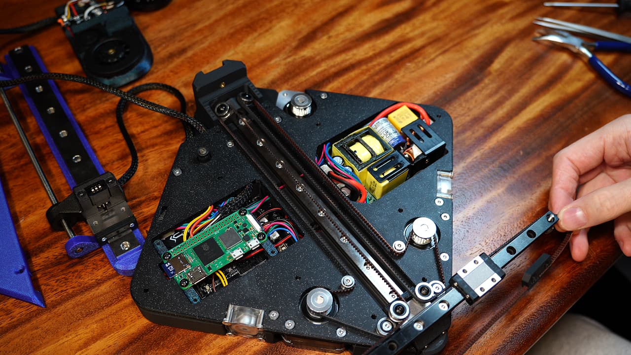
Screw in the tensioner
 Push the tensioner towards the Z block, then fix the tensioner in place with a screw. This should be loose.
M325mm
Push the tensioner towards the Z block, then fix the tensioner in place with a screw. This should be loose.
M325mm -
Thoroughly test
 Thoroughly test and tune the belt tension. When you feel that the friction is negligible, it's ready.
 -
Install top plates
 Drop in the two top plates.
 -
Fasten the outer screws
 Fasten the top plates to the chassis on the 6 outer holes along the edges.
M320mm
Fasten the top plates to the chassis on the 6 outer holes along the edges.
M320mm -
Fasten the inner screws
 Fasten the top plates to the motors on the 4 inner holes. Bonus points if you fabricate 15mm countersinks for a better fit.
M314mm
Fasten the top plates to the motors on the 4 inner holes. Bonus points if you fabricate 15mm countersinks for a better fit.
M314mm -
Attach the tool head
 Drop on the tool head.
 -
Screw on the tool head
 Screw on the tool head.
M314mm
Screw on the tool head.
M314mm -
Attach the belt clip
 Flip over the printer and attach the clip with two screws.
M38mm
Flip over the printer and attach the clip with two screws.
M38mm -
Attach the Z idler arm
 Attach the z idler arm. To make the bearing stack, on a 14mm wafer head, drop a big bearing, medium shim, big bearing, and medium shim.
M314mm
Attach the z idler arm. To make the bearing stack, on a 14mm wafer head, drop a big bearing, medium shim, big bearing, and medium shim.
M314mm -
Attach the Z axis
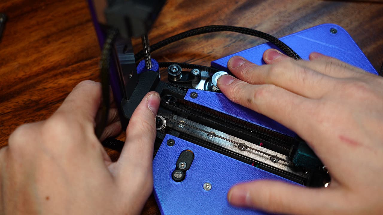 Hook the Z axis drive belt on the pulley. Drop the Z axis into place. Tighten the idler arm.
 -
Screw in Z axis
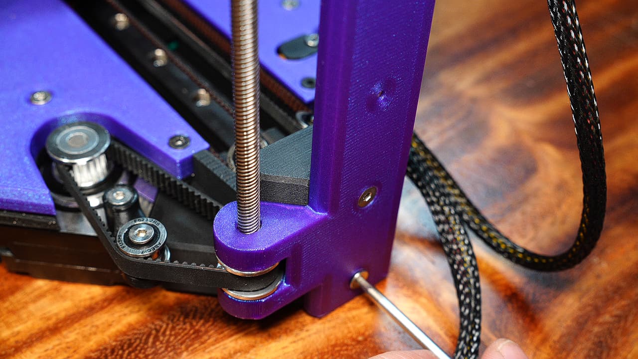 Screw in the Z axis. Rev B uses two button heads instead of the countersinks shown in the picture.
M316mm
Screw in the Z axis. Rev B uses two button heads instead of the countersinks shown in the picture.
M316mm -
Rough up bowden tube
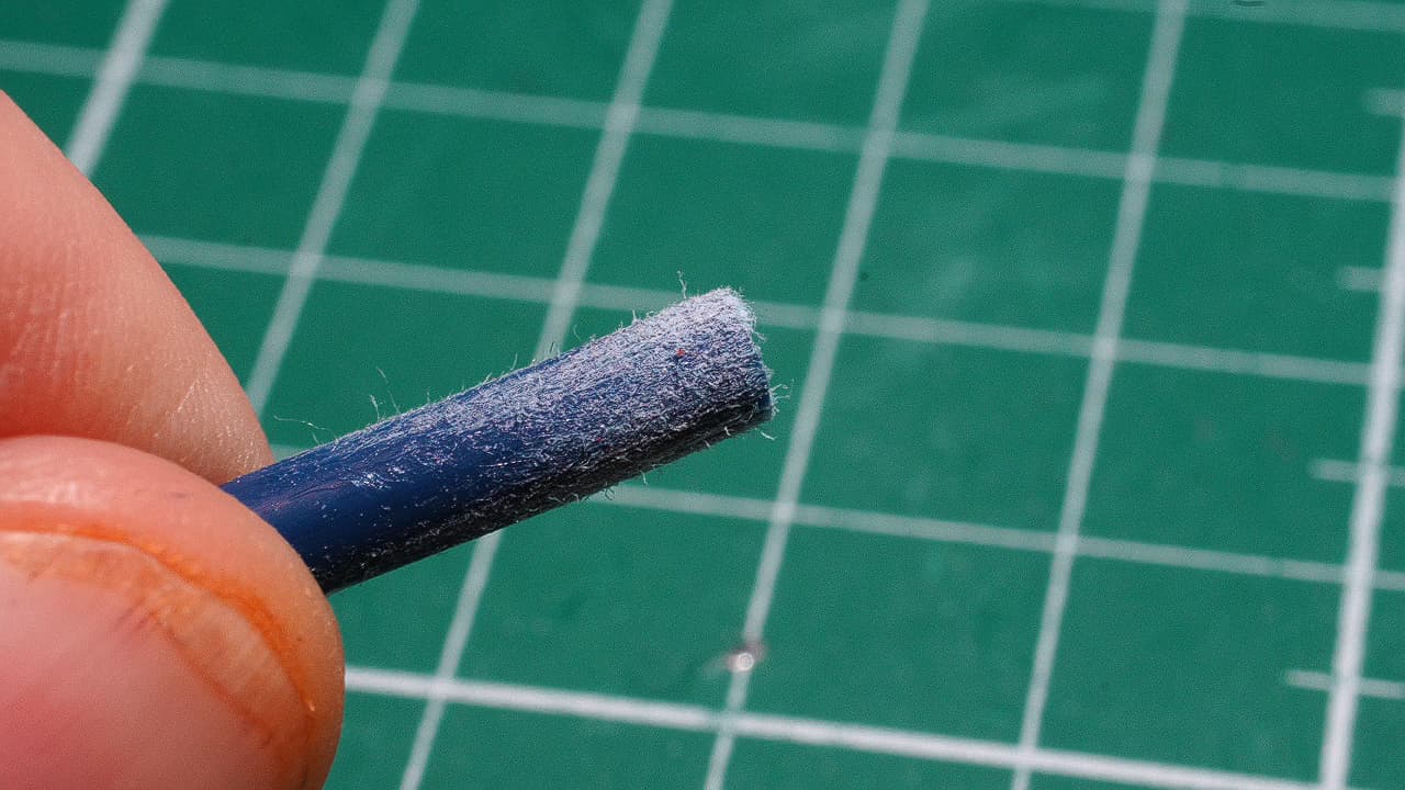 Rough up at least 1cm of the bowden tube.
 -
Pour glue on bowden tube
 Pour a generous amount of glue on the end of the bowden tube.
 -
Insert the bowden tube
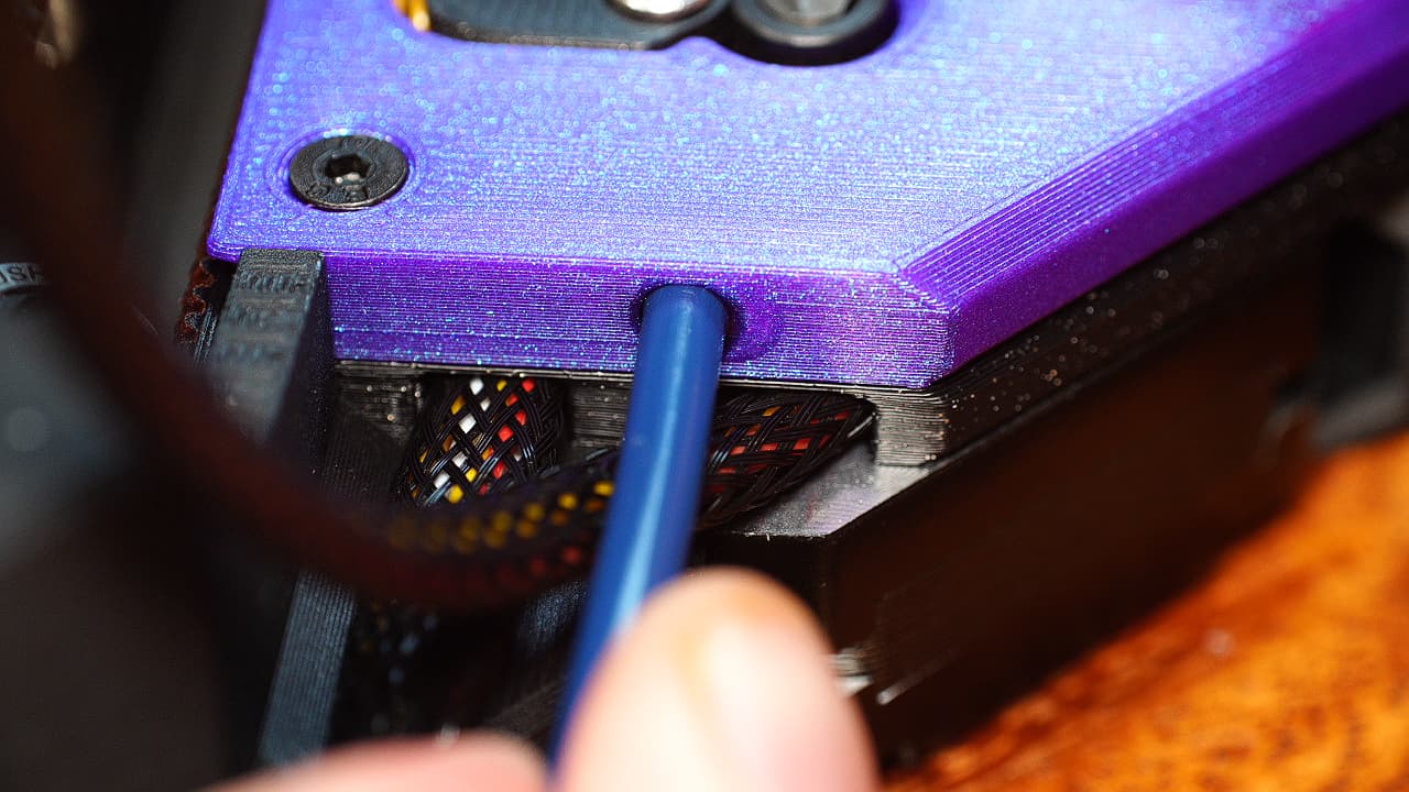 Insert the bowden tube into the top plates. There is a lot of clearance, so the glue will go all the way down.
 -
Zip tie the bowden tube
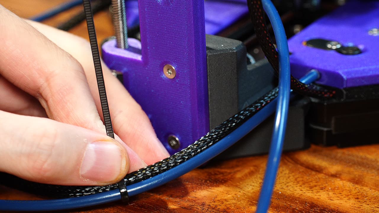 Zip tie the bowden tube with 2 zip ties, one at 10cm, another at 20cm.
 -
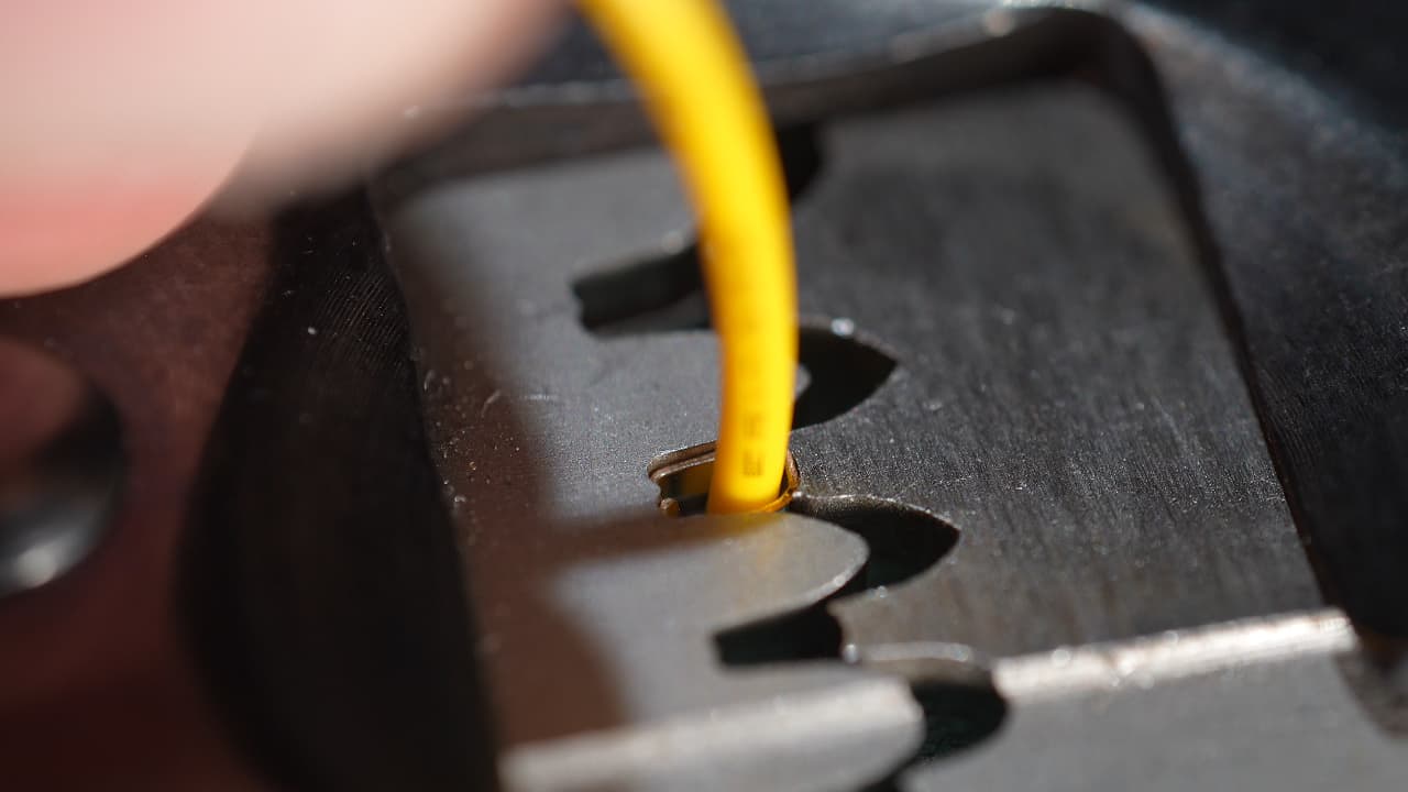
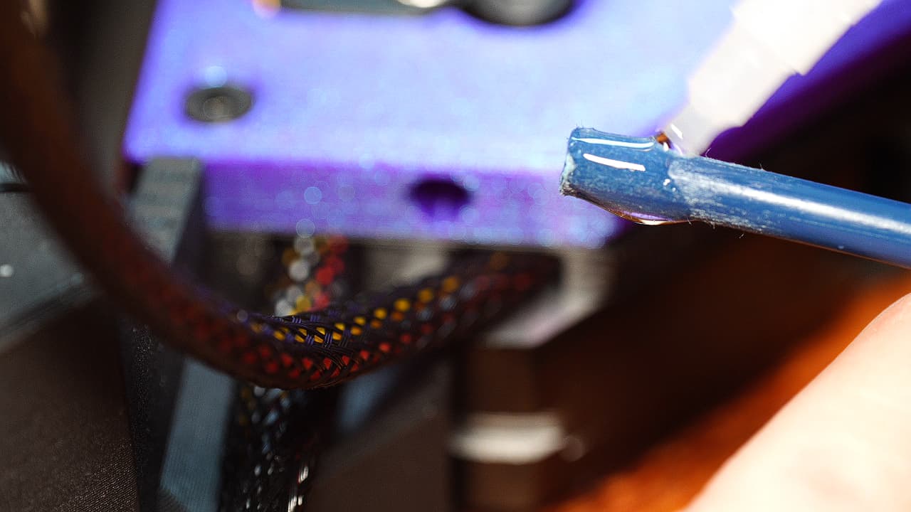
Mark the bowden tube
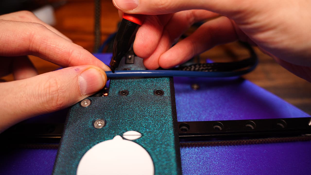 Holding the tube approximately where it needs to go, mark the bowden tube as pictured.
 -
Cut the bowden tube
 SNIP, SNIP! The end needs to be as straight as possible.
 -
Insert bowden tube
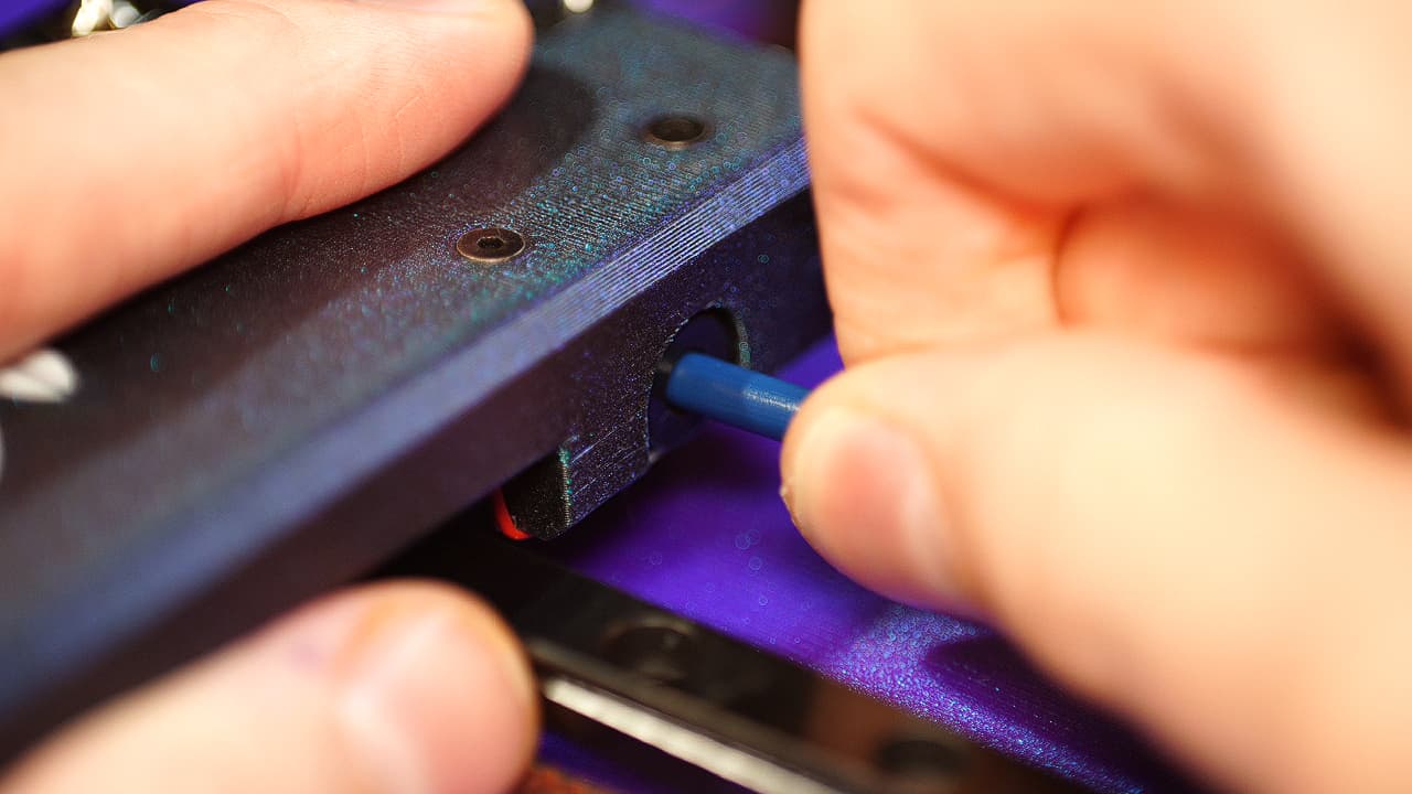 Insert the bowden tube all the way into the tool end.
 -
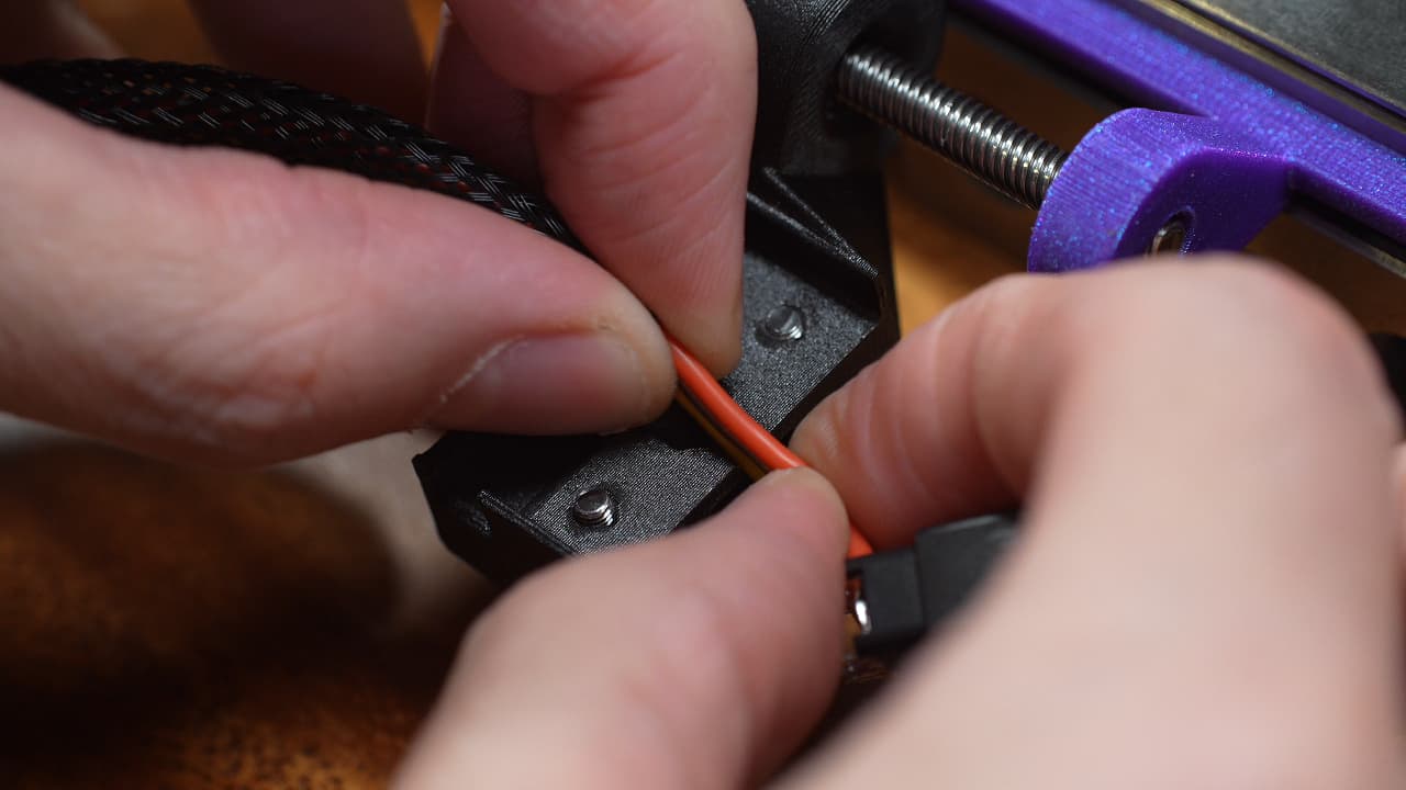
Insert the clip
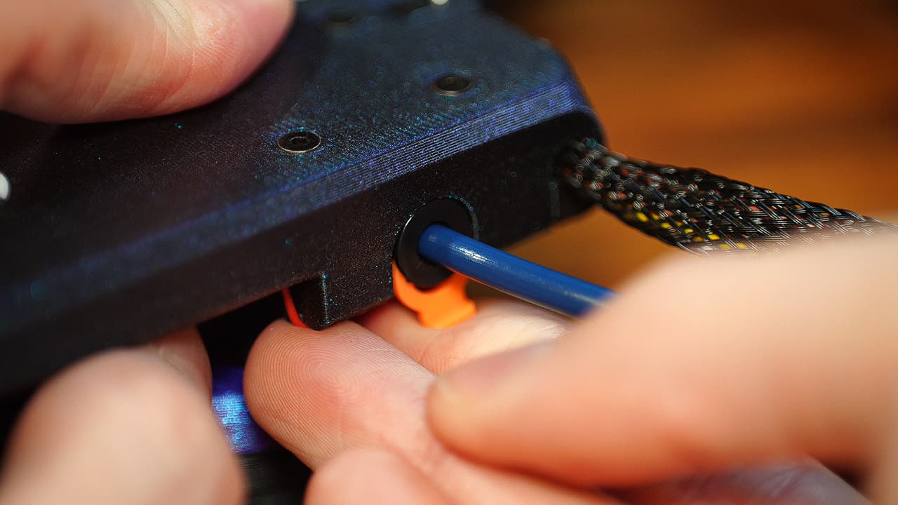 While still putting pressure on the bowden tube, pull out the collar and install the orange clip.
 -
Attach the bed holder
 Attach the bed holder to the Z carriage with the two captive screws.
 -
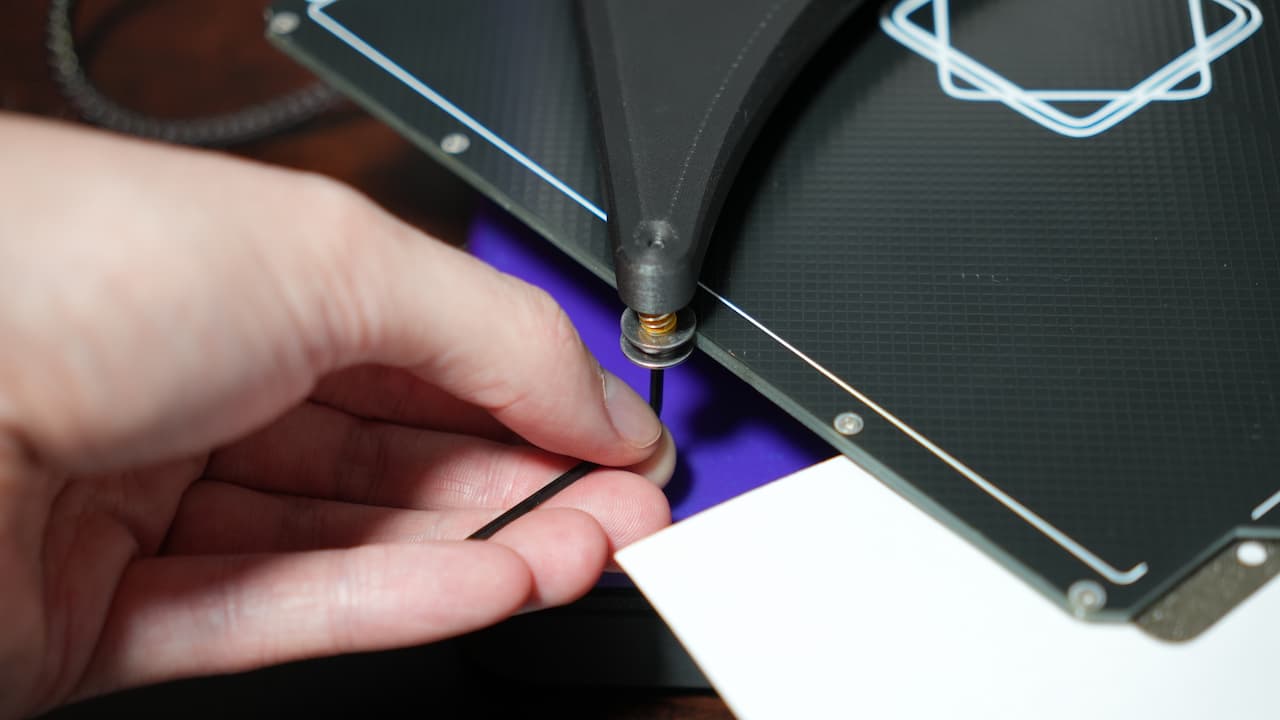
Slide in the bed
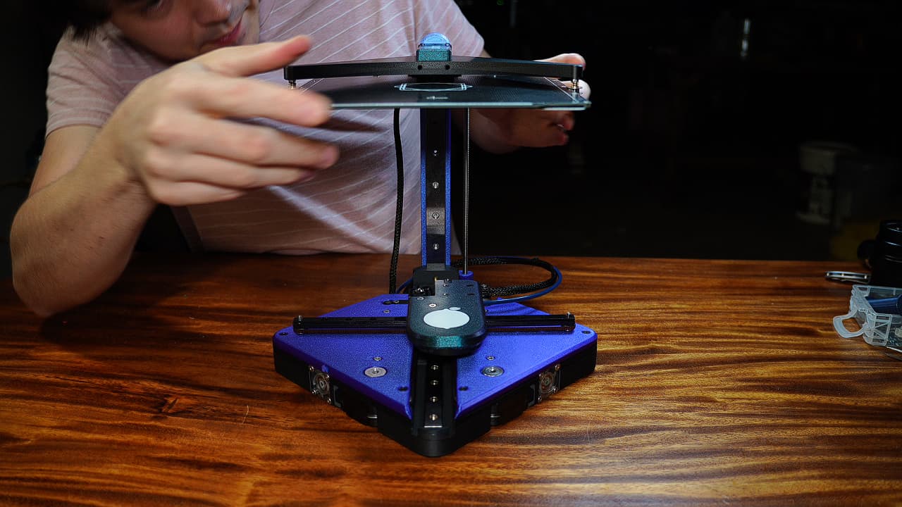 Slide the bed into the spring-loaded posts.
 -
Add the spool holder
O P T I O N A L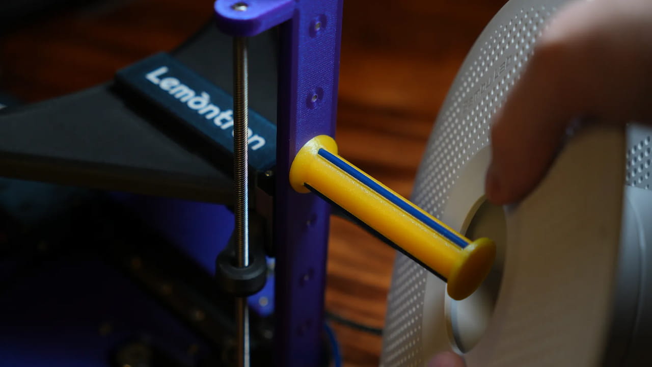 Attach the spool holder through the unpopulated 4th hole on the Z axis.
M340mmThis one is an upgraded model designed by @AngryTaco!
Attach the spool holder through the unpopulated 4th hole on the Z axis.
M340mmThis one is an upgraded model designed by @AngryTaco! -
You've reached the end!
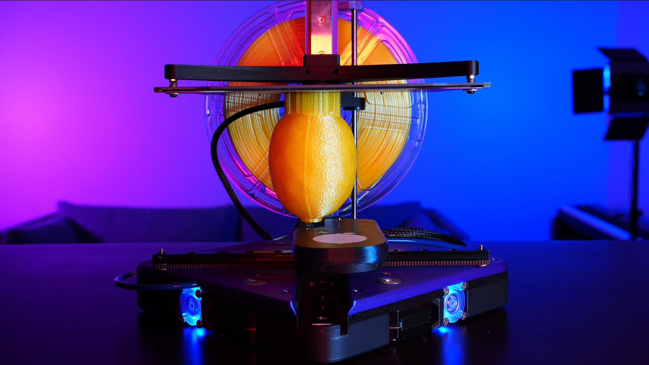 You just built the whole thing. Now wash up, you're probably covered in solder fumes.
 -
Sike you've not reached the end!
 Use the handy guide to do your one-time calibration.
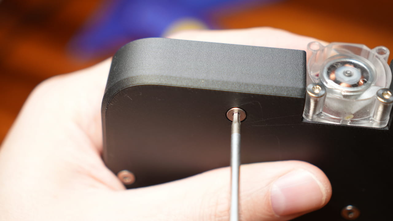
Follow the old machinists tapping tip, which is to drive the screw in, back it out, and
drive it in some more, over and over. This is the best way to ensure you can reuse the plastic threads.
Note for the armchair experts who cry about ferrules
If I hear one more idiotic comment about your stupid ferrules, I will find a tiny ferrule
for your tiny benis and clamp it so hard that you'll wish I would use the iron instead.
Electrical Shock Warning
If caution is not exercised, this device has the potential to cause harm through injuries, burns, and
electrical shocks. Do not become complacent!
But loose belt? Is Lemontron a moron?
You should feel the elasticity, and you should not be able to strum the belt. Why? Because it's not CoreXY!
With only one belt and the same amount of friction total.
Surely there's a better way?
Sometimes the simple solutions are the best. With the absurd contact patch of about 2cm², the glue will hold
the tube until the end of time.